
Measurement system for front and back edge positions of engine guide vane

A guide vane and measurement system technology, applied in the direction of mechanical measuring devices, measuring devices, mechanical devices, etc., can solve the problems of low detection efficiency, many dial indicators, limited detection range, etc., and achieve convenient operation, simple structure, The effect of full cross-section inspection

Inactive Publication Date: 2018-12-11
AECC AVIATION POWER CO LTD
View PDF7 Cites 3 Cited by
  • Summary
  • Abstract
  • Description
  • Claims
  • Application Information

AI Technical Summary

Problems solved by technology

However, this detection method has disadvantages: first, due to the limitation of the length of the part, the short blade can only detect two sections, and the long blade can detect three or four sections, and the detection range is limited; second, the detection section Many blades require many dial gauges, complex operation and low detection efficiency; third, the structure of the measuring tool is complex
Another detection method is to use three-coordinate measurement for detection. This method is only suitable for batch measurement of finished parts, not suitable for parts detection during process processing.

Method used


Image

  • Measurement system for front and back edge positions of engine guide vane
  • Measurement system for front and back edge positions of engine guide vane
  • Measurement system for front and back edge positions of engine guide vane

Examples


Embodiment Construction

[0035] The present invention is described in further detail below in conjunction with accompanying drawing:

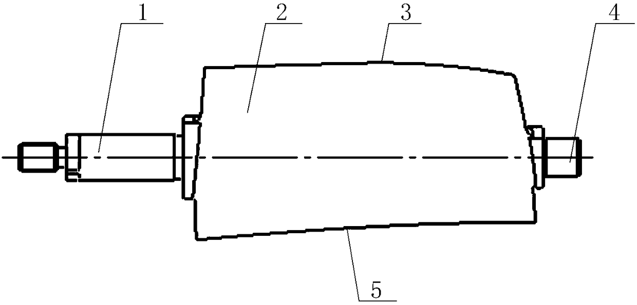
[0036] see figure 1 , the guide vane includes upper journal 1, airfoil 2, trailing edge 3, lower journal 4 and leading edge 5; upper journal 1 is connected to one end of blade airfoil 2, and the other end of blade airfoil 2 is connected to lower journal 4 ; One side of the blade body 2 is the trailing edge 3 , and the other side is the leading edge 5 . The present invention measures the position of the front and rear edges of the guide vane, that is, measures the distance from the front or rear edge of a certain section of the guide vane to the central axis of the guide vane.

[0037] The position measurement system of the front and rear edges of the guide vane includes a clamping device and a measuring device;

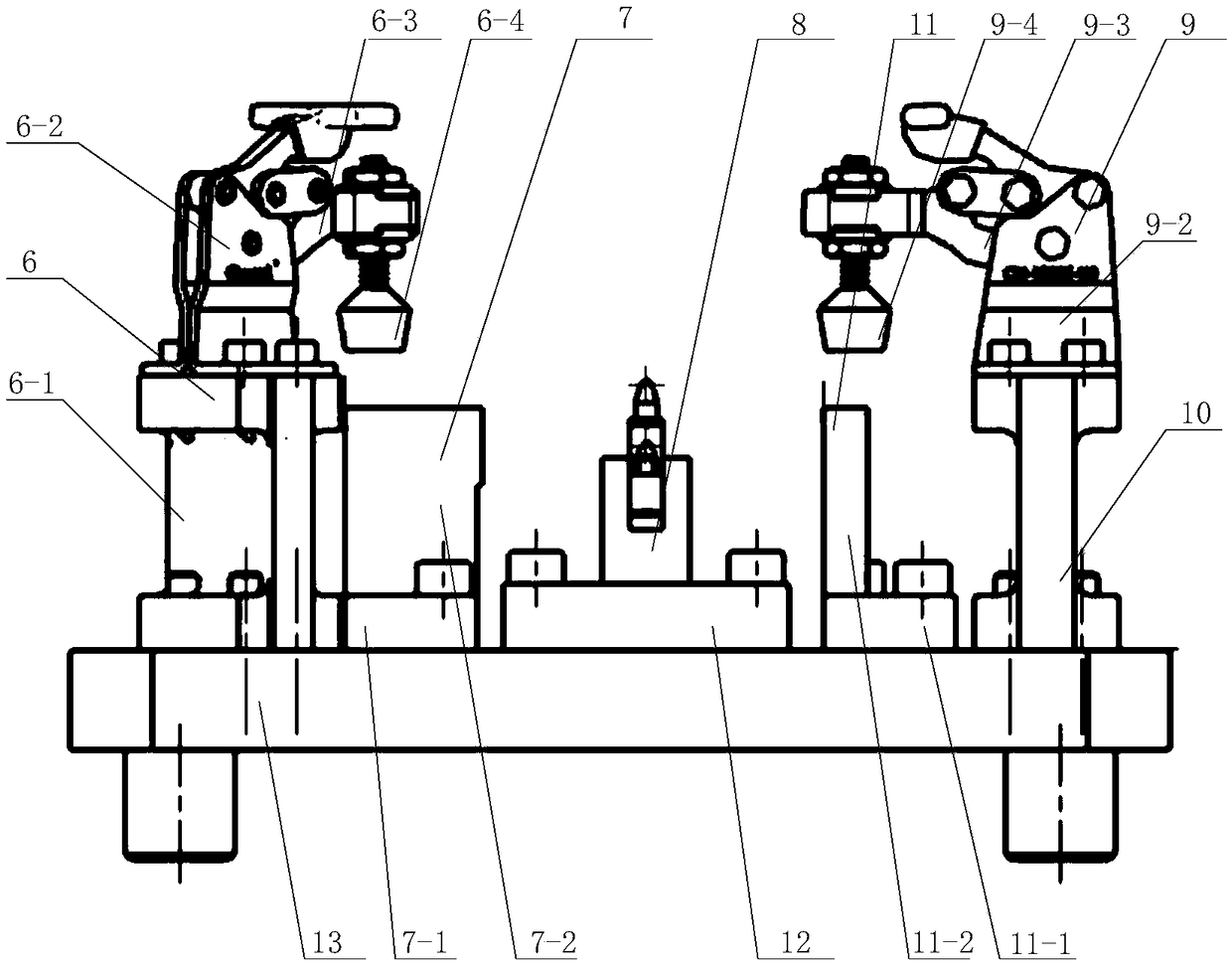
[0038] see figure 2 , The clamping device includes a first pressing mechanism 6 , a first positioning mechanism 7 , an airfoil positioning mechanism 8 , a...


PUM


Abstract

The invention discloses a measurement system for front and back edge positions of an engine guide vane. The system comprises a clamping device and a measuring device, the clamping device comprises a positioning mechanism and a compressing mechanism, the positioning mechanism and the compressing mechanism compress the two ends of the guide vane cooperatively, and a blade body positioning mechanismis positioned in an intermediate support blade in the guide vane. After that the clamping device clamps the guide vane, a measuring device measures the size in the front and back edge positions of a to-be-measured cross section. The measurement system designed aimed at the size in the front and back edge positions of the guide vane is simple in structure and convenient to operate and can detect the front and back edges of the vane in the whole cross section with high efficiency.

Description

【Technical field】 [0001] The invention belongs to the technical field of engine guide vane measurement, in particular to a measurement system for the front and rear positions of the engine guide vane. 【Background technique】 [0002] With the development of my country's aviation industry, the performance requirements of the engine are constantly improving, so the blade body curvature of the engine turbine blade is also increasing. see figure 1 , the leading edge and trailing edge of the turbine blade are composed of multiple spatial curves with large curvature changes, and the airflow flows through the surface of the airfoil profile, so the accuracy of the airfoil and the leading and trailing edges is very high. [0003] The general device for measuring the front and rear edges is to set a dial indicator frame at a fixed section, and use standard parts to align the back of the watch and detect the front and rear edges. However, this detection method has disadvantages: first...

Claims


Application Information

Patent Timeline
Patent Type & Authority Applications(China)
IPC IPC(8): G01B5/00
CPCG01B5/0002G01B5/003
Inventor 刘金凤李飞侯飞龙郭海杜家燕郭洋张静怡高峰利
Owner AECC AVIATION POWER CO LTD
Learn More