Adjustable constant-pressure safe exhaust valve

An adjustable and exhaust valve technology, applied in safety valves, balance valves, valve devices, etc., can solve problems such as accidents, complicated operation methods and processes, and excessive tire inflation, so as to increase the exhaust volume and avoid The effect of rapidly increasing the pressure and expanding the exhaust area

Active Publication Date: 2018-12-11
李阳
View PDF6 Cites 2 Cited by
  • Summary
  • Abstract
  • Description
  • Claims
  • Application Information

AI Technical Summary

Problems solved by technology

[0002] Industrial production involves the use of gas and air pressure equipment. The equipment for controlling the air pressure value and safety protection in production is more complicated and costly. For equipment that needs to change the air pressure value frequently, the operation method and process are more complicated during operation.
The traditional exhaust valve is limited by the exhaust method and exhaust direction of the exhaust hole, so the exhausted gas cannot be effectively disposed of.
[0003] For example, when inflating a vehicle tire, the tire pressure is usually determined by using a barometer or personal experience, but improper operation leads to excessive inflation of the vehicle tire, so that the pressure in the tire suddenly increases and a puncture or other Accidents happen from time to time

Method used


Image

  • Adjustable constant-pressure safe exhaust valve
  • Adjustable constant-pressure safe exhaust valve
  • Adjustable constant-pressure safe exhaust valve

Examples


Embodiment 1

[0028] Such as figure 1 As shown, the adjustable constant pressure safety exhaust valve of this embodiment includes an inner pipe 21, an outer pipe 22, a valve plug 23, a spring 24, a valve cap 25 and an exhaust pipe 26; the inner pipe 21 is provided with an air inlet 211 And the inner hole 212, the air inlet 211 and the inner hole 212 are all arranged along the axial direction of the inner pipe 21, the air inlet 211 and the inner hole 212 communicate and extend to the two ends of the inner pipe 21 respectively; and the diameter of the air inlet 211 The diameter is smaller than the diameter of the inner hole 212 , so that a shoulder is formed at the junction of the air inlet hole 211 and the inner hole 212 . The valve plug 23 is arranged in the inner hole 212, and the valve plug 23 can slide in the inner hole 212, and the shoulder can limit the valve plug 23; the side wall of the inner hole 212 is provided with a notch 221, and the notch 221 It is cut by a saw blade, so that ...

Embodiment 2

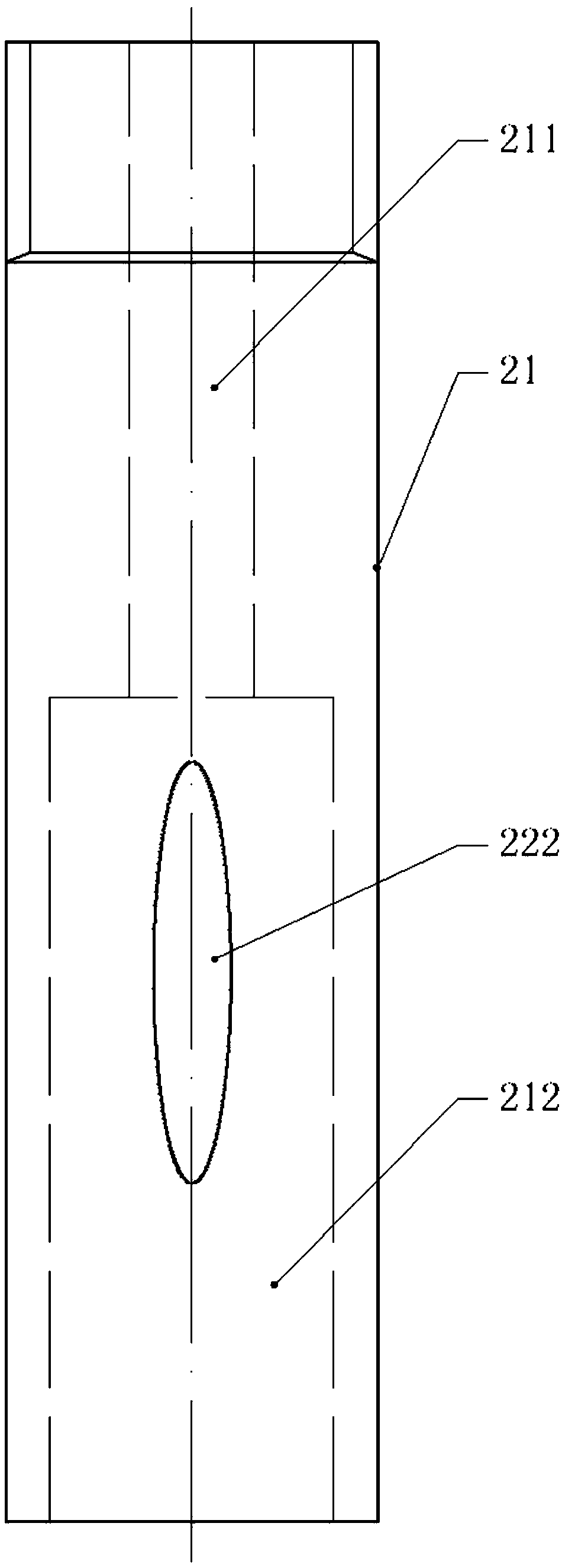
[0037] Such as image 3 As shown, the difference between the second embodiment and the first embodiment is that the side wall of the inner hole 212 is provided with an oval through hole 222 instead of the notch 221, so that the exhaust groove is composed of the through hole 222 and the inner wall of the outer tube 22. composition. The length of the long axis direction of the through hole 222 is greater than the height of the valve plug 23, so that when the valve plug 23 slides in the inner hole 212, the two ends of the through hole 222 can be respectively located on the upper and lower sides of the valve plug 23, so that the through hole 222 connects the air intake hole 211 with the inner hole 212 to achieve the exhaust effect. Since the through hole 222 is elliptical, when the valve plug 23 slides in the inner hole 212, the area of ​​the through hole 222 above the valve plug 23 will gradually increase, thereby achieving the effect of enlarging the exhaust area of ​​the exhau...

Embodiment 3

[0039] Such as Figure 4 , Figure 5 As shown, the difference between the third embodiment and the first embodiment is that the cross-section of the inner hole 212 is a square, and the valve plug 23 cooperates with the inner hole 212, so that the valve plug 23 can only slide relative to the axial direction of the inner hole 212 And can not rotate in inner hole 212. An air pressure mechanism is also provided between the bonnet 25 and the inner pipe 21. The air pressure mechanism includes a turbine 27 arranged in the air inlet 211, an air pressure rod 232 fixed on the lower end surface of the valve plug 23, and an air pressure rod 232 sleeved outside the air pressure rod 232 and The air pressure sleeve 251 welded on the bottom of the bonnet 25; the upper part of the air pressure rod 232 is provided with a cavity, the cavity is provided with a piston 28, the side wall of the piston 28 is provided with a guide groove, and the side wall of the cavity is provided with The guide ed...


PUM


Abstract

The invention relates to the technical field of valves, and particularly discloses an adjustable constant-pressure safe exhaust valve. The adjustable constant-pressure safe exhaust valve comprises anexhaust assembly and a valve cap connected with the exhaust assembly; a stepped hole is formed in the exhaust assembly, the two ends of the stepped hole extend to the two end surfaces of the exhaust assembly correspondingly, the small end of the stepped hole is an air inlet hole, the large end of the stepped hole is an inner hole communicating with the outside, a shoulder portion is formed at thejoint between the air inlet hole and the inner hole, a valve plug capable of abutting against the shoulder portion of the stepped hole and plugging the air inlet hole is arranged in the inner hole, anexhaust groove is formed in the side wall of the inner hole, the length of the exhaust groove in the axial direction of the inner hole is larger than the height of the valve plug, and a spring whichwith two ends abutted against the valve plug and the valve cap correspondingly is arranged in the inner hole. According to the valve, the rapid pressure reduction can be achieved under the condition that the pressure is suddenly increased, so that the phenomenon that the phenomenon of tire burst caused by the fact that the pressure intensity inside a tire is rapidly increased is avoided.

Description

technical field [0001] The invention relates to the technical field of valves, in particular to an adjustable constant pressure safety exhaust valve. Background technique [0002] Industrial production involves the use of gas and air pressure equipment. The equipment for controlling the air pressure value and safety protection in production is more complicated and costly. For equipment that needs to change the air pressure value frequently, the operation method and process are more complicated during operation. . The traditional exhaust valve is limited by the exhaust method and exhaust direction of the exhaust hole, so the exhausted gas cannot be effectively disposed of. [0003] For example, when inflating a vehicle tire, the tire pressure is usually determined by using a barometer or personal experience, but improper operation leads to excessive inflation of the vehicle tire, so that the pressure in the tire suddenly increases and a puncture or other Accidents happen fr...

Claims


Application Information

Patent Timeline
Patent Type & Authority Applications(China)
IPC IPC(8): F16K17/04F16K17/06F16K37/00
CPCF16K17/044F16K17/048F16K17/0493F16K17/06F16K37/0016
Inventor 李阳
Owner 李阳
Why Eureka
Try Eureka