External liquid storage box and household appliance
A technology for household appliances and liquid storage boxes, which is applied to household appliances, household cleaning devices, applications, etc., can solve the problems of insufficient installation of multi-functional electronic modules, insufficient space in the lower part of a control panel seat, and easy accumulation of dust and dirt on detergents. Achieve the effect of high liquid outflow efficiency, simple structure, convenient replacement and cleaning
- Summary
- Abstract
- Description
- Claims
- Application Information
AI Technical Summary
Problems solved by technology
Method used
Image
Examples
Embodiment 1
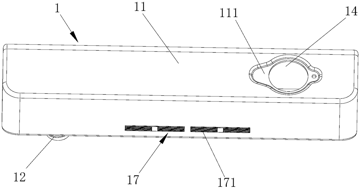
[0053] Such as figure 1 with figure 2 As shown, the ventilation unit 13 described in this embodiment includes an opening 14 and a sealing cover 15 installed on the opening 14. The side surface of the sealing cover 15 facing the opening 14, that is, the lower surface of the sealing cover 15 is provided with a The opening 14 is a ventilation structure that communicates the inside and outside of the box body 11 .
[0054] Preferably, the opening 14 is arranged on the box body 11, and the sealing cover 15 can be opened and closed to cover and install on the opening 14. One side of the sealing cover 15 is connected with the box body 11 through a hinge part. The sealing cover 15 of example is connected with the box body by the connecting rod 150 that is movably plugged in respectively on the sealing cover 15 and the side wall of the box body 11;
[0055] Preferably, at least one claw 10 is provided on the surface of the sealing cover 15 facing the opening 14 to engage with the op...
Embodiment 2
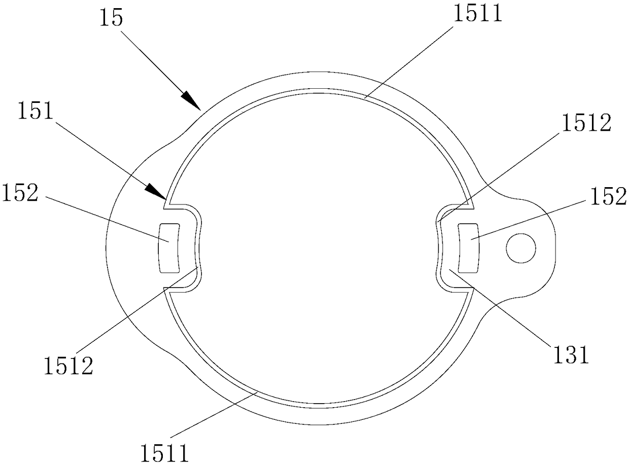
[0057] The ventilation structure described in this embodiment is configured as a ventilation channel 131 extending from the opening 14 to the outer peripheral direction of the sealing cover 15 . Preferably, the ventilation channel 131 is integrally formed on the lower surface of the sealing cover 15 (see image 3 ).
[0058] Further, the ventilation channel is a groove structure opened on the lower surface of the sealing cover. Alternatively, the ventilation channel is formed by the cooperation of the support provided on the lower surface of the sealing cover and supported on the side wall of the box around the opening (not shown in the figure).
[0059] Alternatively, the ventilation channel is a conduit independently installed on the surface of the sealing cover facing the opening, one end communicates with the opening, and the other end faces the outer periphery of the sealing cover and communicates with the outside world (not shown in the figure).
Embodiment 3
[0061] Such as image 3 with Figure 4 As shown, the lower surface of the sealing cover 15 described in this embodiment is provided with a sealing rib 151 , and the sealing rib 151 cooperates with the side wall 111 of the box body around the opening 14 to form a ventilation channel 131 . The side wall 111 of the box body around the opening 14 is designed to be concave, so that the sealing cover 15 can be embedded in the concave.
[0062] The sealing rib 151 includes a part of the first rib 1511 that is set near the edge of the lower surface of the sealing cover 15 and is supported on the side wall 111 of the box body around the opening, and another part from the first rib 1511 toward the center of the sealing cover 15. The second rib 1512 that shrinks and is located above the opening 14 is supported by the first rib 1511 through the vertical gap between the second rib 1512 and the edge of the opening 14 so that the lower surface of the sealing cover 15 is in contact with the ...
PUM
 Abstract
Description
Claims
Application Information
 - Generate Ideas
- Intellectual Property
- Life Sciences
- Materials
- Tech Scout
- Unparalleled Data Quality
- Higher Quality Content
- 60% Fewer Hallucinations
Browse by: Latest US Patents, China's latest patents, Technical Efficacy Thesaurus, Application Domain, Technology Topic, Popular Technical Reports.
© 2025 PatSnap. All rights reserved.Legal|Privacy policy|Modern Slavery Act Transparency Statement|Sitemap|About US| Contact US: help@patsnap.com


