Returning back suction type fiber filter and sewage treatment method thereof
A sewage treatment method and fiber filter technology, which are applied in the fields of water/sewage multi-stage treatment, water/sludge/sewage treatment, filtration treatment, etc., can solve the problem of high cost, high manufacturing difficulty, and complex structure of the fiber turntable filter. And other issues
- Summary
- Abstract
- Description
- Claims
- Application Information
AI Technical Summary
Problems solved by technology
Method used
Image
Examples
Embodiment approach
[0026] The back-and-forth anti-suction fiber filter of the present invention has two kinds of implementation modes: one is the back-and-forth lifting anti-suction fiber filter, and the other is the back-and-forth horizontal back-suction fiber filter, two implementations below The working principle of the method is explained separately:
[0027] A sewage treatment method for a back-and-forth back-suction fiber filter. The back-and-forth back-suction fiber filter adopts a back-and-forth lifting back-suction fiber filter, and all filter holes are arranged symmetrically in two groups along the horizontal direction. A group of mud suction devices are installed at the front end of each group of filter plates. Under the limit action of the lifting guide rail and the driving action of the lifting mechanism, the suction head of the mud suction device is flush with the filter plate and abuts against the front of the filter cloth. Its movement track is parallel to the filter plate, and t...
Embodiment approach 1
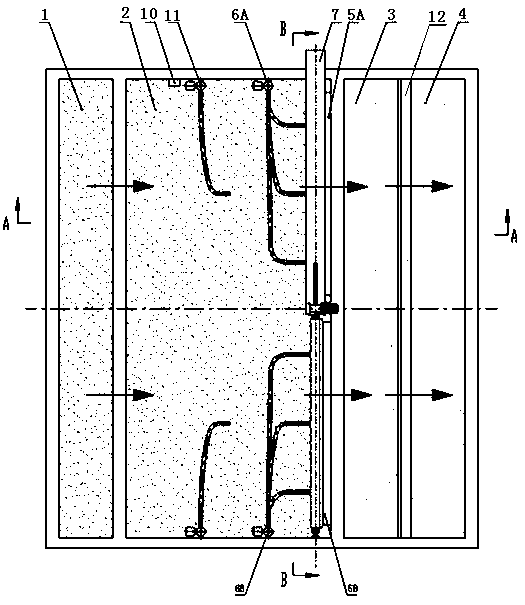
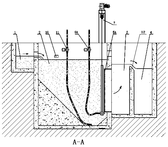
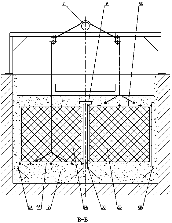
[0081] For small-scale sewage treatment systems, the structure of a back-and-forth lifting back-suction fiber membrane filter involved in Embodiment 1 of the present invention is as follows: Figure 1-12 As shown, it includes a water inlet tank 1, a sewage tank 2, a filtrate tank 3, a water outlet tank 4, two groups of filter plates 5A and 5B, two groups of mud suction devices 6A and 6B, 6A and 6B, a lifting mechanism 7, lifting guide rails 8A, 8B and 8C, limit sensor 9, liquid level sensor 10 and sedimentation sludge pump 11 and other parts. The water inlet tank 1 is located at the front end of the sewage tank 2, and the sewage flows into the sewage tank 2 slowly and steadily through the water inlet between the water inlet tank 1 and the sewage tank 2; the sewage tank 2 is a rectangular structure, and a slope is provided at the bottom to make sediment The sludge is concentrated, which is convenient for suction and cleaning; the back end of the sewage pool 2 is connected to th...
specific Embodiment approach 2
[0086] For some large sewage treatment systems, multiple filter plates and multiple mud suction devices can also be used. The specific structure is as follows: Figure 11 , 12 shown. Its main structure is consistent with the specific embodiment 2, and its main difference from the specific embodiment is that each filter plate 5A01, 5A02, ..., 5A0m, 5B01, 5B02, ..., 5B0m corresponds to a dredge 6A01, 6A02 , ..., 6A0x, 6B01, 6B02, ..., 6B0x; each mud suction device 6A01, 6A02, ..., 6A0x, 6B01, 6B02, ..., 6B0x is connected with a stay rope, and the stay rope 704 passes through the The pulley is connected with the lifting drive 702, driven by the lifting drive 702, the mud suction devices 6A01, 6A02, ..., 6A0x, 6B01, 6B02, ..., 6B0x move at a constant speed, bounded by the horizontal center of the filter plate group, on the same side The movements of the mud suction devices 6A01, 6A02, ... 6A0x or 6B01, 6B02, ..., 6B0x are synchronized and consistent, and the movements of the mud...
PUM
 Abstract
Description
Claims
Application Information
 - Generate Ideas
- Intellectual Property
- Life Sciences
- Materials
- Tech Scout
- Unparalleled Data Quality
- Higher Quality Content
- 60% Fewer Hallucinations
Browse by: Latest US Patents, China's latest patents, Technical Efficacy Thesaurus, Application Domain, Technology Topic, Popular Technical Reports.
© 2025 PatSnap. All rights reserved.Legal|Privacy policy|Modern Slavery Act Transparency Statement|Sitemap|About US| Contact US: help@patsnap.com


