Manufacturing process of machine tool material receiving device

A material receiving device and production process technology, which is applied in the direction of manufacturing tools, metal processing, metal processing equipment, etc., can solve the problems of easy turnover of materials, affecting material receiving, affecting the normal operation of lathes, etc., to increase kinetic energy and ensure smoothness. Effect

Inactive Publication Date: 2018-12-11
CHONGQING HONGGANG CNC MACHINE TOOL
View PDF8 Cites 0 Cited by
  • Summary
  • Abstract
  • Description
  • Claims
  • Application Information

AI Technical Summary

Problems solved by technology

However, the above-mentioned material receiving mechanism has the following problems: 1. Nowadays, the material receiving plate arranged at an inclination is mostly used to receive the material, relying on the gravity of the material itself to make it slide to the next link, but due to the length of the material receiving plate It is relatively long, and when the material is sliding on the material receiving plate, it is easy to get stuck, which will affect the material receiving of the following materials, causing multiple materials to accumulate on the guide plate, and eventually affect the normal operation of the lathe
2. When turning disc materials, the side wall of the disc is generally provided with a ring groove. The ring groove is not in the middle of the disc material. After receiving the material, the detection of the ring groove will be set. Mechanism, but when the disc material is received by the above-mentioned material catcher, it will be directly dropped on the material receiving box after being grabbed by the manipulator, and the disc material will turn over, because the height error makes it impossible for the detection mechanism to detect Ring groove, which will affect the test results
Therefore, it is necessary to process a machine tool material receiving device, so as to be able to solve the problem that the material is easy to get stuck, and the material is easy to turn over so that the circular groove cannot be detected

Method used


Image

  • Manufacturing process of machine tool material receiving device
  • Manufacturing process of machine tool material receiving device
  • Manufacturing process of machine tool material receiving device

Examples


Embodiment 1

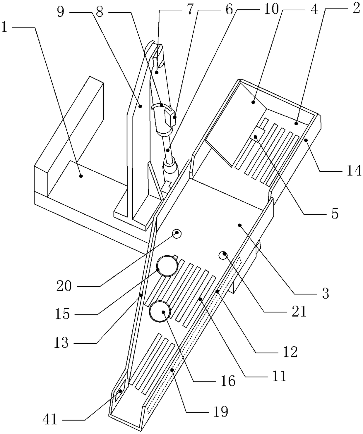
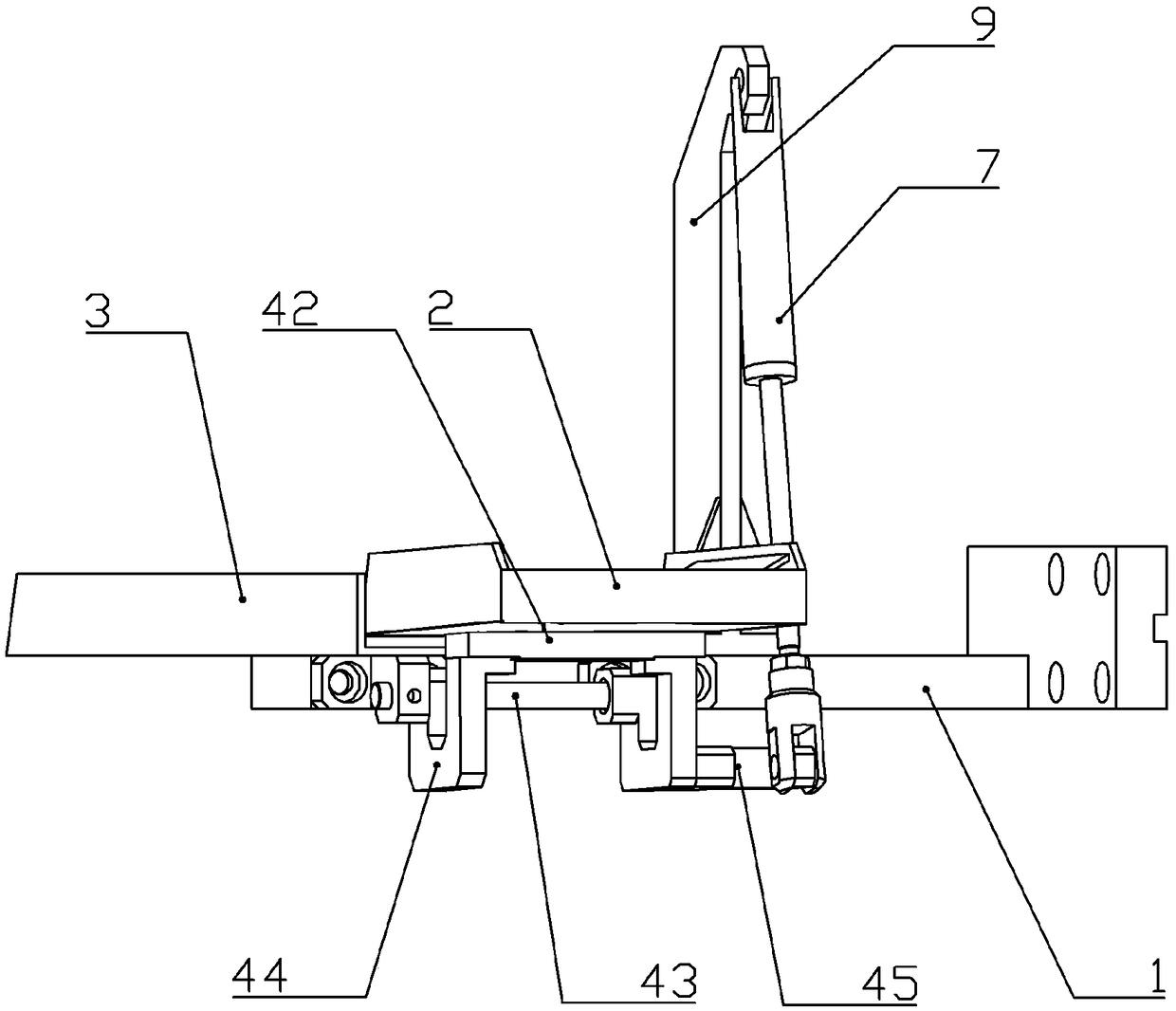
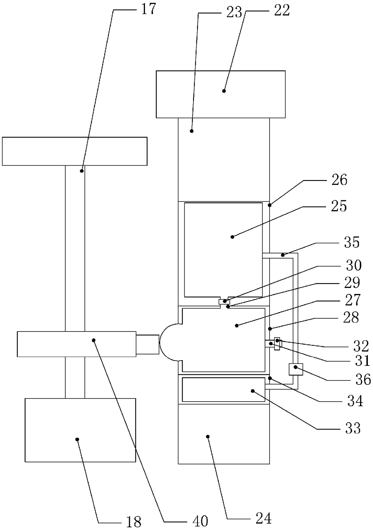
[0025] Such as figure 1 , figure 2 , image 3 with Figure 4 Shown: The automatic feeding device for machine tool materials, including a fixed frame 1, a rotary feeding tray 2 and a fixed feeding tray 3, the fixed feeding tray 3 is set obliquely downward, and the fixed feeding tray 3 is connected to the fixed frame 1, The lower end of the fixed receiving tray 3 is provided with a discharge port, the discharge end of the rotary receiving tray 2 is in contact with the feeding end of the fixed receiving tray 3, and the fixed receiving tray 3 and the rotary receiving tray 2 A plurality of discharge holes 11 are opened. There is a drive mechanism on the fixed frame 1, and a guide plate 4 is provided on the left side of the revolving tray 2, and the guide plate 4 is set obliquely downward, and a pressure sensor is arranged on the side of the revolving tray 2 close to the guide plate 4 5 and the controller. The drive mechanism includes an air pump 6 and a push cylinder 7, the a...

Embodiment 2

[0033] The difference between embodiment 2 and embodiment 1 is that a U-shaped block 44 is integrally formed on the back of the rotary receiving tray 2 . By setting in this way, the strength of the rotary receiving tray 2 can be enhanced, and the number of parts can be reduced.


PUM


Abstract

The invention relates to the technical field of machine tool manufacturing and discloses a manufacturing process of a machine tool material receiving device. The manufacturing process of the machine tool material receiving device includes the following steps of machining and installation; for the step of machining, a rotary material receiving tray and a fixed material receiving tray are processedso that both the rotary material receiving tray and the fixed material receiving tray are of a groove shape, and one side of the rotary material receiving tray is fixedly connected with a guide plate;for the step of installation, the fixed material receiving tray is tilted and fixedly installed on a fixed rack, a discharge end of the rotary material receiving tray is placed on a feed end of the fixed material receiving tray, the upper surface of the fixed rack is fixedly connected with a first support rod whose upper end is hinged with a push cylinder, and the lower end of a piston rod of thepush cylinder is rotably connected to one side of the rotary material receiving tray. The manufacturing process of the machine tool material receiving device has the advantages of avoiding material jamming and making receiving work operate normally, avoiding flipping of disc-like materials, and enabling a later detection mechanism to normally detect a circular groove.

Description

technical field [0001] The invention relates to the technical field of machine tool manufacturing, in particular to a manufacturing process of a machine tool material receiving device. Background technique [0002] CNC machine tools are one of the commonly used equipment in the field of mechanical processing. They have attracted much attention because of their high processing efficiency and precise processing. At present, CNC machine tools include a material distribution mechanism, a processing mechanism, a grabbing and feeding mechanism, a material receiving mechanism, and a testing mechanism. Among them, the material receiving mechanism sends the processed materials to the next link. The progress of the entire lathe machining process. The current material receiving mechanism is relatively large and occupies a relatively large space, which is only suitable for large machine tools. [0003] For this reason, Chinese patent announcement number is that CN207358676U discloses ...

Claims


Application Information

Patent Timeline
IPC IPC(8): B23Q7/00B23B41/00B23B35/00
CPCB23Q7/00B23B35/00B23B41/00
Inventor 汪传宏
Owner CHONGQING HONGGANG CNC MACHINE TOOL
Why Eureka
Try Eureka