Determination of channel osnr and channel osnr margin at real network conditions

An optical transmission network, practical technology, applied in electrical components, electromagnetic wave transmission systems, transmission systems, etc., can solve the problem of not giving an estimated optical signal-to-noise ratio margin, etc.

Inactive Publication Date: 2018-12-07
XIEON NETWORKS SARL
View PDF7 Cites 7 Cited by
  • Summary
  • Abstract
  • Description
  • Claims
  • Application Information

AI Technical Summary

Problems solved by technology

However, no details are given therein regarding the correct estimation of the OSNR margin during network operation while taking into account the different technical issues mentioned above
[0014] Given this, there is room for technical improvement in determining the OSNR margin for a given optical link in an optical transport network

Method used


Image

  • Determination of channel osnr and channel osnr margin at real network conditions
  • Determination of channel osnr and channel osnr margin at real network conditions
  • Determination of channel osnr and channel osnr margin at real network conditions

Examples


example 1

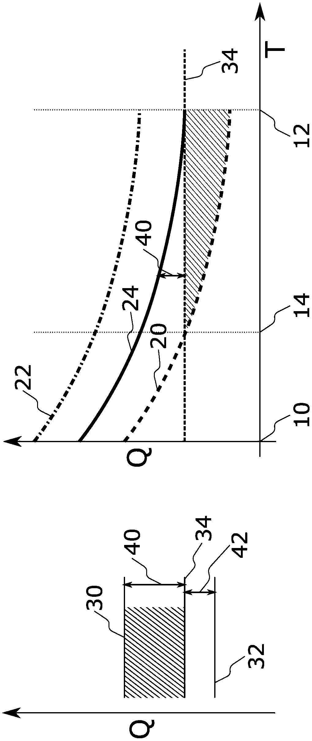
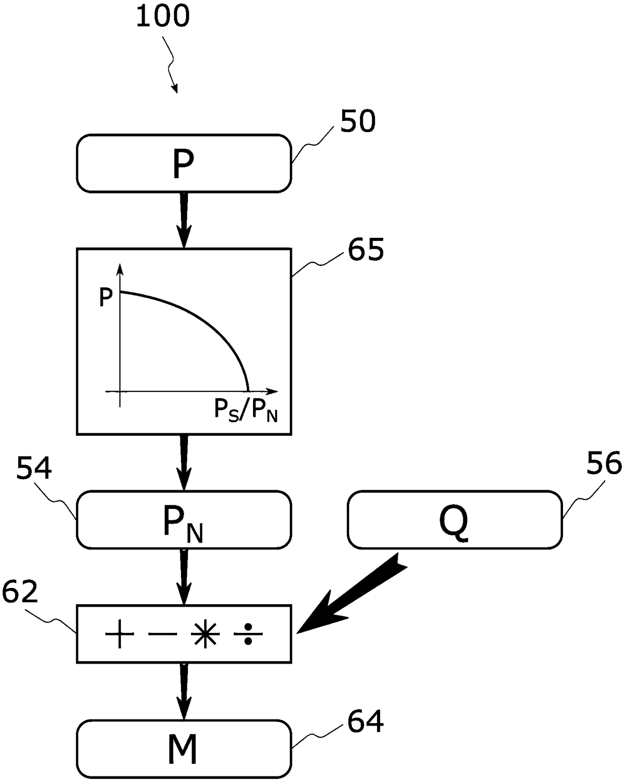
[0096] According to a first example, the performance value P may correspond to the BER before FEC related to the total noise power on the optical link for the channel under consideration, i.e. to the secondary noise power value P according to the predetermined relationship F N , so that the auxiliary noise power value P N The value of is mapped to the value of the performance parameter P:

[0097] F:1 / N→P, where

[0098] where P S represents the signal power at the receiver of the channel under consideration. The predetermined relationship can then be reversed to map any pre-FEC BER measurement (i.e., any performance value) to a corresponding secondary noise power value P N :

[0099] f -1 :P→1 / N

[0100] The OSNR correlation value Q can be measured by the OSA. Subsequently, the auxiliary noise power value P due to ASE can be obtained from N The corresponding contribution of , which is the only one detectable by OSA:

[0101]

[0102] Because in this case the O...
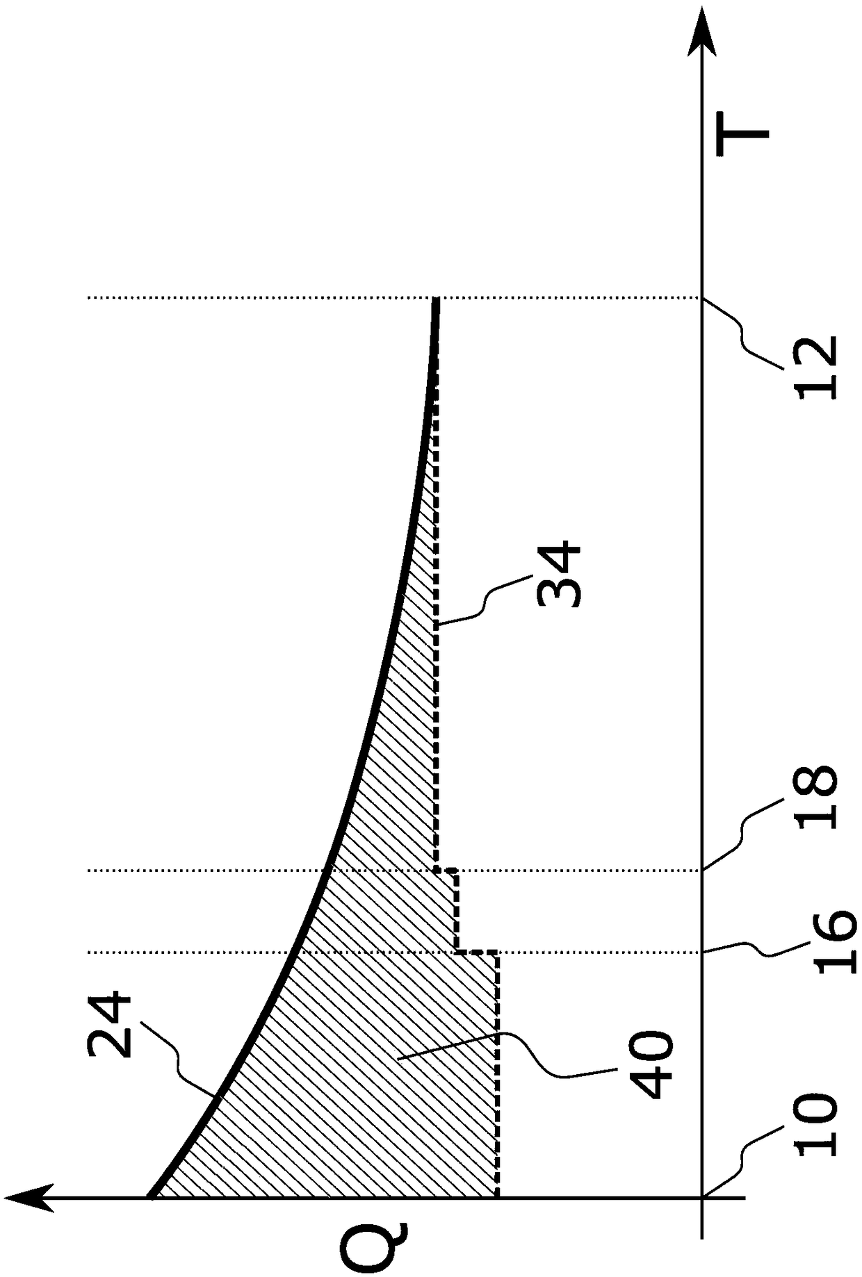
example 2

[0117] According to the second example, two performance values ​​(P 1 ,P 2 ).

[0118] Under a first operating condition, eg for a first value of signal power, a first performance value P is obtained 1 , and said first performance value corresponds to the BER before FEC related to the total secondary noise power on the optical link for the channel under consideration, i.e. corresponds to the first secondary noise power value P according to the predetermined relationship F N1 , so that the first auxiliary noise power value P N1 The value of is mapped to the value of the first performance parameter P 1 :

[0119] F:N 1 →P 1 ,in

[0120] Under a second operating condition, eg for a second value of signal power, a second performance value P is obtained 2 , and said second performance value corresponds to the BER before FEC related to the total secondary noise power on the optical link for the channel under consideration, i.e. corresponds to the second secondary noise p...


PUM


Abstract

A method of determining contributions of different sources of signal degradation for optical signals transmitted over an optical link in an optical transmission system, comprising measuring a performance value (P) of a signal transmission on said optical link, deriving, from the performance value, an auxiliary noise power value (PN) based on a predetermined relationship between the performance value (P) and the auxiliary noise power value (PN), wherein the auxiliary noise power value (PN) comprises contributions of amplified spontaneous emission power (PA) generated on the optical link and a link-related equivalent noise power contributions (PL) representing other sources of signal degradation upon transmission on the optical link, measuring or deriving an OSNR-related value (Q) for the signal transmission on the optical link, wherein the OSNR-related value (Q) corresponds to or is at least indicative of an actual OSNR on the optical link, and distinguishing, based on the auxiliary noise power value (PN) and on the OSNR-related value (Q) between noise power contributions of amplified spontaneous emission and link-related equivalent noise power contributions.

Description

technical field [0001] The invention belongs to the field of optical fiber communication. Specifically, the present invention relates to a method for determining an optical signal-to-noise ratio (OSNR) and OSNR margin of a given optical link in an optical transmission network, and a method configured to determine a given The corresponding equipment of the OSNR margin of the optical link. Background technique [0002] A typical optical transport network includes multiple nodes interconnected by optical links. Each node of an optical transmission link may include one or more optical components, and the optical links interconnecting the nodes are typically optical fibers. A key aspect of optical network communication is to ensure that optical data can be transmitted between nodes over optical links of an optical communication network with a degree of quality such that regardless of any possible sources of attenuation or signal degradation that may affect the transmission of o...

Claims


Application Information

Patent Timeline
Patent Type & Authority Applications(China)
IPC IPC(8): H04B10/079
CPCH04B10/07953
Inventor 尤拉伊·斯洛伐克沃尔夫冈·施莱尔马西米兰·赫尔曼恩里科·托伦戈
Owner XIEON NETWORKS SARL
Why Eureka
Try Eureka