
Array image pick-up module set, molded circuit board assembly thereof, manufacturing method and electronic device

A circuit board assembly and camera module technology, which is applied in the direction of electrical components, color TV parts, TV system parts, etc., can solve the pollution of the photosensitive area of ​​the photosensitive element, and the size of the dual-lens camera module cannot be effectively controlled. Zoom out, the focal length and zoom range of the dual-lens camera module are reduced, etc.

Pending Publication Date: 2018-12-07
NINGBO SUNNY OPOTECH CO LTD
View PDF0 Cites 0 Cited by
  • Summary
  • Abstract
  • Description
  • Claims
  • Application Information

AI Technical Summary

Problems solved by technology

[0004] First, these passive components, each of the photosensitive elements and the support are mounted on the same side of the circuit board, and no matter in the length and width direction or height of the dual-lens camera module , between adjacent passive components, between the passive component and the photosensitive component, between adjacent photosensitive components, between the passive component and the bracket, and between the bracket and the A safe distance needs to be reserved between the photosensitive elements, which leads to the fact that the size of the dual-lens camera module in the length and width directions and the size in the height direction cannot be effectively reduced
[0005] Secondly, after mounting each of the photosensitive elements on the circuit board respectively, a group of gold wires need to be formed on at least one side of the photosensitive element through a wire bonding process to conductively connect the photosensitive element and The circuit board, and in order to ensure the wire bonding process and ensure the good typicality of the gold wires formed by the wire bonding process, it is also necessary to reserve a safe distance between the passive components and the gold wires, which further As a result, the length and width dimensions of the dual-lens camera module cannot be effectively reduced
[0006] Third, these passive components and the photosensitive components are located in the same space, which leads to the shedding of the surface of the passive components due to oxidation or the connection position between the passive components and the circuit board. The exfoliated matter easily adheres to the photosensitive area of ​​the photosensitive element, or adheres to the filter element held in the photosensitive path of the photosensitive element, resulting in the undesirable phenomenon of smudged spots.
[0007] Fourth, the support is mounted on the circuit board by a fluid adhesive such as glue applied to the circuit board. During this process, the fluid glue may flow to the The photosensitive area of ​​the photosensitive element, which causes the photosensitive area of ​​the photosensitive element to be polluted
[0008] In addition, the current dual-lens camera module mounts the photosensitive element on the surface of the substrate, which causes the distance between the photosensitive element and the optical lens to be limited to a small range. In order to reduce the height dimension of the dual-lens camera module, it can only be realized by reducing the distance between the photosensitive element and the optical lens, which results in the focal length and zoom range of the dual-lens camera module It is reduced so that it seriously affects the performance and development space of the dual-lens camera module

Method used


Image

  • Array image pick-up module set, molded circuit board assembly thereof, manufacturing method and electronic device
  • Array image pick-up module set, molded circuit board assembly thereof, manufacturing method and electronic device
  • Array image pick-up module set, molded circuit board assembly thereof, manufacturing method and electronic device

Examples


Embodiment Construction

[0169] The following description serves to disclose the present invention to enable those skilled in the art to carry out the present invention. The preferred embodiments described below are only examples, and those skilled in the art can devise other obvious variations. The basic principles of the present invention defined in the following description can be applied to other embodiments, variations, improvements, equivalents and other technical solutions without departing from the spirit and scope of the present invention.

[0170] Those skilled in the art should understand that in the disclosure of the present invention, the terms "vertical", "transverse", "upper", "lower", "front", "rear", "left", "right", " The orientation or positional relationship indicated by "vertical", "horizontal", "top", "bottom", "inner", "outer", etc. is based on the orientation or positional relationship shown in the drawings, which are only for the convenience of describing the present invention...


PUM


Abstract

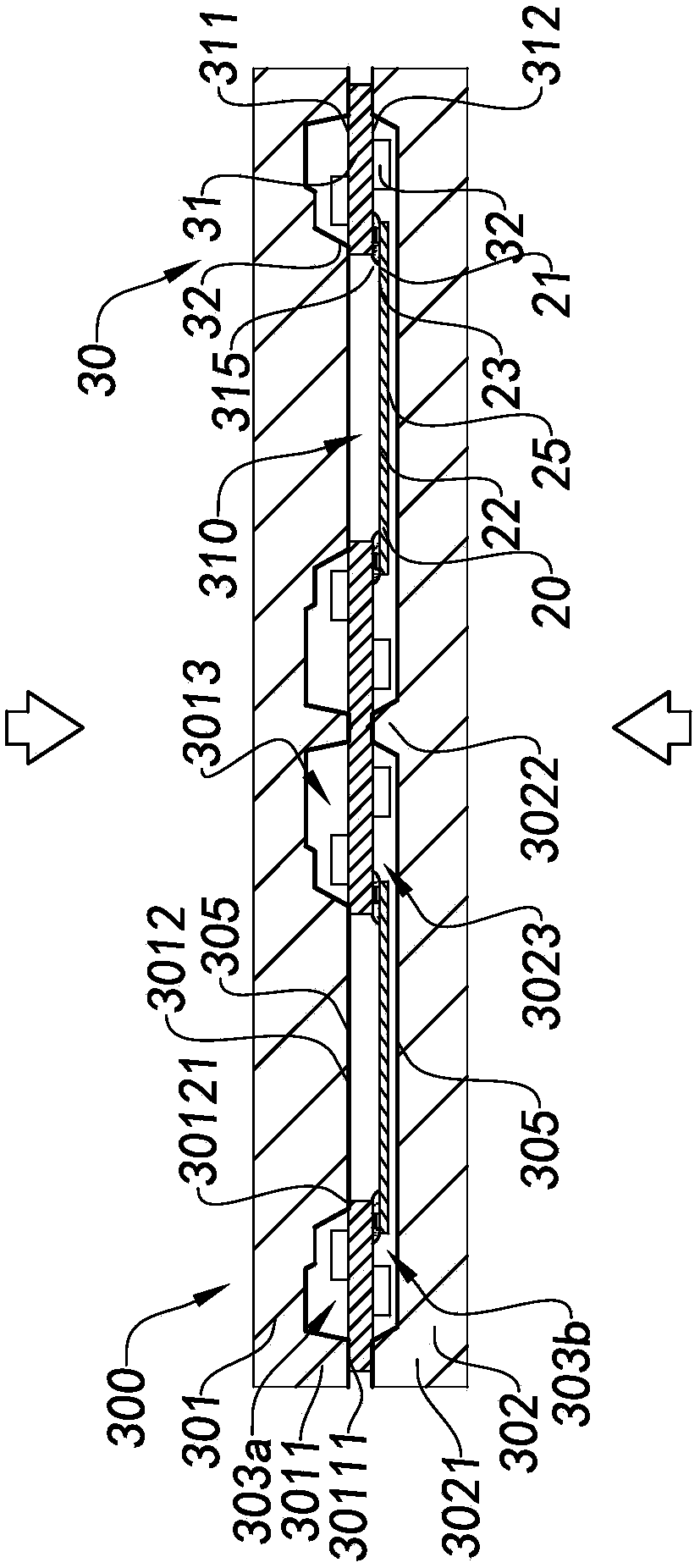
The invention provides an array image pick-up module set, a molded circuit board assembly thereof, a manufacturing method and an electronic device. The image pick-up module set comprises at least oneback molded part, at least two optical lenses, at least two photosensitive elements, and at least one circuit board; the circuit board comprises at least one substrate and at least one electronic component that is conductively connected to the substrate; a part of the non-photosensitive region of each photosensitive element is conductively connected with the substrate at the substrate back surfaceof the substrate, so that the photosensitive region and the other part of the non-photosensitive region of each photosensitive element are corresponding to the substrate channel of the substrate; theback molded part is integrally bonded to at least a portion of the substrate back surface of the substrate; and each optical lens is arranged in the photosensitive path of each photosensitive element.

Description

technical field [0001] The invention relates to the field of optical imaging, in particular to an array camera module and its molded circuit board assembly, manufacturing method and electronic equipment. Background technique [0002] In recent years, dual-lens camera modules have become popular. Compared with single-lens camera modules, the size of dual-lens camera modules is larger. When dual-lens camera modules are applied to portable electronic devices that are becoming thinner and lighter , the large-sized dual-lens camera module not only takes up more space inside the portable electronic device in the length and width direction, but also the lens end of the dual-lens camera module is forced to protrude from the surface of the portable electronic device, for example, for rear For the camera module, the lens end of the dual-lens camera module is forced to protrude from the back of the portable electronic device, and the more the dual-lens camera module has a long focal le...

Claims


Application Information

Patent Timeline
IPC IPC(8): H04N5/225
CPCH04N23/50H04N23/57H04N23/55H04N23/54
Inventor 不公告发明人
Owner NINGBO SUNNY OPOTECH CO LTD
Learn More