Copper bar connection structure

A connection structure and technology of copper bars, applied in the direction of connection, conductive connection, electrical component connection, etc., can solve the problems that the conductive copper bars cannot be electrically connected, and the conductive copper bars cannot be bent and installed.

Pending Publication Date: 2018-12-07
GUANGDONG POWER GRID CO LTD +2
View PDF0 Cites 1 Cited by
  • Summary
  • Abstract
  • Description
  • Claims
  • Application Information

AI Technical Summary

Problems solved by technology

[0005] In view of this, the present invention provides a copper bar connection structure, which solves the technical problems that the conductive copper bars in the existing bus bars cannot be electrically conducted and the conductive copper bars cannot be bent and installed

Method used


Image

  • Copper bar connection structure
  • Copper bar connection structure
  • Copper bar connection structure

Examples


Embodiment Construction

[0026] The invention provides a copper bar connection structure, which solves the technical problems that the conductive copper bar in the existing bus bar cannot be electrically conducted and the conductive copper bar cannot be bent and installed.

[0027] The technical solutions in the embodiments of the present invention will be described clearly and completely below. Obviously, the described embodiments are only a part of the embodiments of the present invention, rather than all the embodiments. Based on the embodiments of the present invention, all other embodiments obtained by those of ordinary skill in the art without creative work shall fall within the protection scope of the present invention.

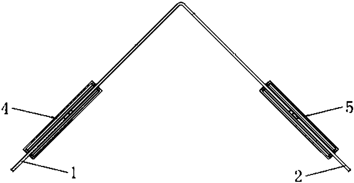
[0028] See figure 1 with figure 2 , The embodiment of the present invention provides a copper bar connection structure, including an L-shaped electrical connection copper bar, a first connector 4, a second connector 5, the L-shaped electrical connection copper bar includes mutually...


PUM


Abstract

The invention relates to the technical field of bus devices, in particular, to a copper bar connection structure. Provided in the invention is a copper bar connection structure comprising an L type electric copper bar, a first connector, a second connector, a first conductor and a second conductor. The L type electric copper bar includes a first electric copper bar and a second electric copper barthat are connected mutually; the first conductor is arranged inside the first connector; and the second conductor is arranged inside the second connector. The first connector sleeves the outer surface of the first electric copper bar connected with the first conductor electrically; and the second connector sleeves the outer surface of the second electric copper bar connected with the second conductor electrically. With the copper bar connection structure provided by the invention, technical problems that the conductive copper bar of the existing bus can not be in electric conduction and the conductive copper bar can not bent for installation are solved.

Description

Technical field [0001] The invention relates to the technical field of busbar devices, in particular to a copper bar connection structure. Background technique [0002] With the emergence of modern engineering facilities and equipment, the electricity consumption of all walks of life has increased rapidly, especially the emergence of numerous high-rise buildings and large workshops. Traditional cables as transmission conductors can no longer meet the requirements in large current transmission systems. The parallel use of multiple cables brings a lot of inconvenience to the installation and connection on site. The plug-in bus has emerged as a new type of power distribution wire. Compared with traditional cables, it fully demonstrates its superiority in high current transmission. At the same time, due to the adoption of new technology and new technology, the two busbars are greatly reduced. The contact resistance and temperature rise of the end connection and the junction of the b...

Claims


Application Information

Patent Timeline
IPC IPC(8): H01R11/09H01R11/01H01R4/28
CPCH01R4/28H01R11/01H01R11/09
Inventor 刘玮刘琨郭志军曾耿晖李一泉陈桥平王增超王育学朱晓华徐锡斌闫晓蕊张建华
Owner GUANGDONG POWER GRID CO LTD
Why Eureka
Try Eureka