Novel button switch

A button and switch technology, applied in the direction of electric switches, electrical components, circuits, etc., can solve problems such as inconsistency, the influence of on and off accuracy, contact deviation between the contact part and the clamping part, etc.

Active Publication Date: 2014-02-19
HUIZHOU GREETECH ELECTRONICS
View PDF4 Cites 1 Cited by
  • Summary
  • Abstract
  • Description
  • Claims
  • Application Information

AI Technical Summary

Problems solved by technology

[0002] A push button switch currently used in the market includes a body, the body has a receiving cavity, a clip is installed in the receiving cavity, the clip has two clamping parts, and two terminals are installed in the body, each The terminal has a contact portion exposed in the receiving cavity, and the clip is driven to move up and down, so that the clamping portion contacts the contact portion, thereby realizing electrical conduction between the two terminals, When it needs to be disconnected, the spring drives the clip to move upwards, so that the clamping part is separated from the contact part. However, the force properties on the upper and lower sides of this symmetrical clip are different, one is friction, and the other is friction. Spring recovery force causes different resistances when the clip moves up and down, and the left-right height deviation of the left-right symmetrical structure itself leads to deviations when the contact part contacts the clamping part, resulting in the accuracy of connection and disconnection Affected, and there is a certain degree of difficulty in the production of this kind of left-right symmetrical clip

Method used


Image

  • Novel button switch
  • Novel button switch
  • Novel button switch

Examples


Embodiment Construction

[0024] The following will clearly and completely describe the technical solutions in the embodiments of the present invention with reference to the accompanying drawings in the embodiments of the present invention. Obviously, the described embodiments are only some, not all, embodiments of the present invention. Based on the embodiments of the present invention, all other embodiments obtained by persons of ordinary skill in the art without making creative efforts belong to the protection scope of the present invention.

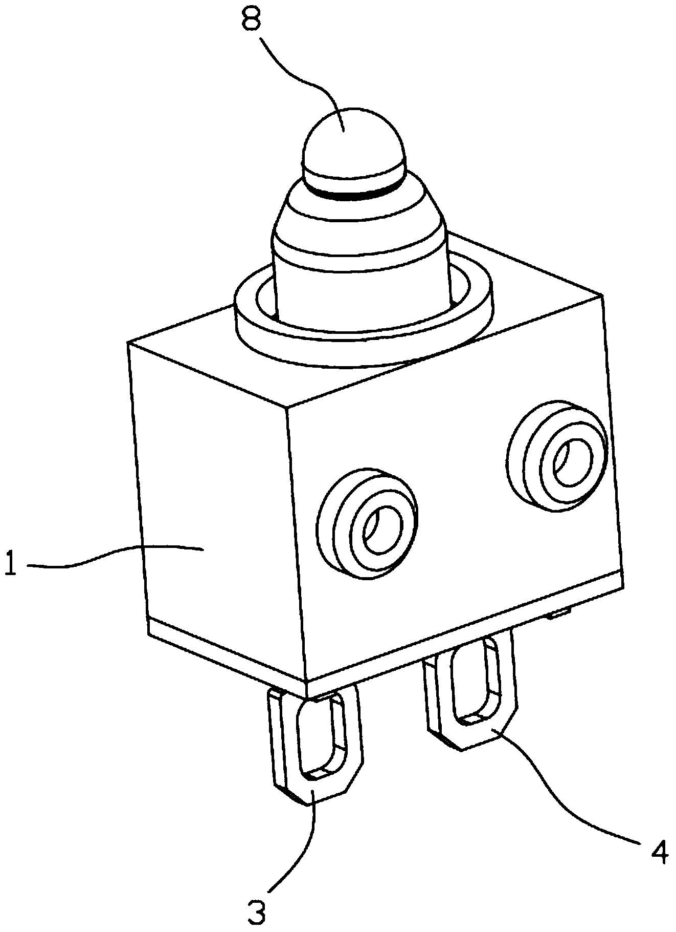
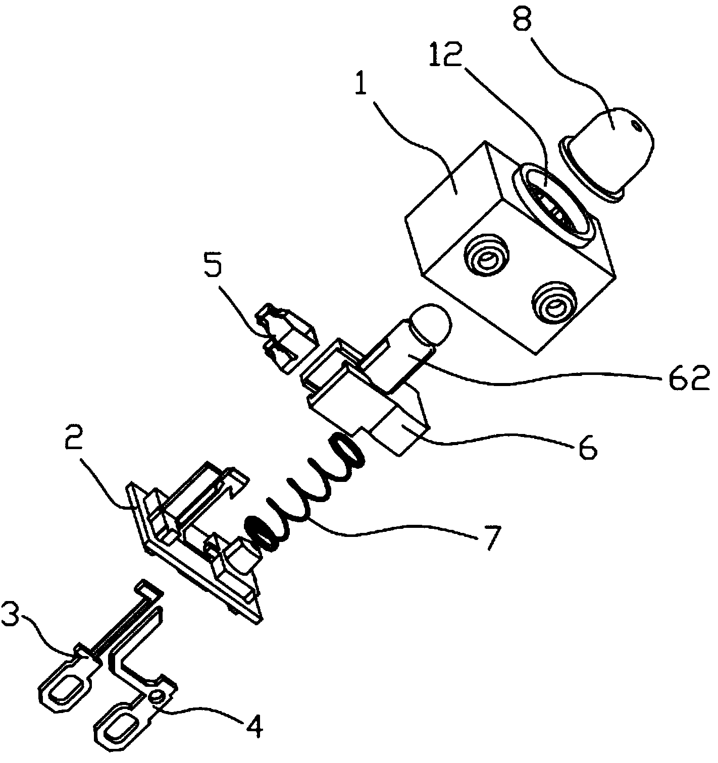
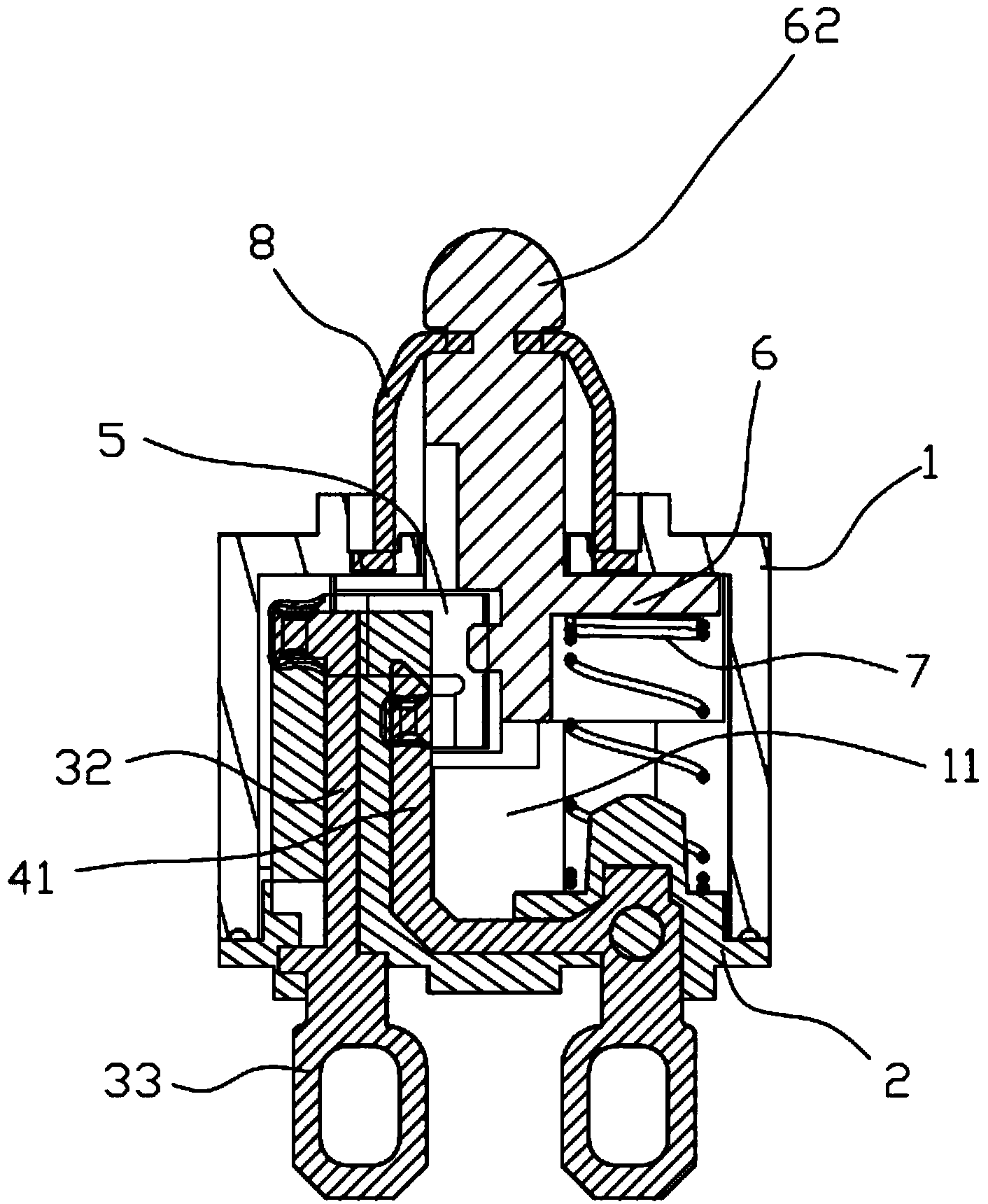
[0025] Such as Figure 1 to Figure 8 , the embodiment of the present invention provides a new type of push button switch, also called a waterproof switch, which has a waterproof function, and it includes a plastic shell 1, a base 2, a first terminal 3, a second terminal 4, a clip 5, A pressing piece 6 , a spring 7 and a sealing ring 8 .

[0026] The plastic case 1 has a receiving chamber 11, the plastic case 1 is made of plastic material, and the receiving ch...


PUM


Abstract

The invention provides a novel button switch which comprises a rubber shell, a base, a first terminal, a second terminal and a clamp, wherein the first terminal is provided with a first contact portion, the second terminal is provided with a second contact portion contained in the rubber shell, the second contact portion is located below the first contact portion, the clamp is provided with a main body portion, the upper end of the main body portion is provided with first clamping portions in a leftward extending mode, and the lower end of the main body portion is provided with second clamping portions in a leftward extending portion. In an initial state, the first clamping portions make contact with the first contact portion to drive the clamp to move downward, the first clamping portions are separated from the first contact portion, the second clamping portions make contact with the second contact portion all the time to enable the first clamping portions to make contact with or be separated from the first contact portion, and electric connection or separation between the first terminal and the second terminal is further achieved. The clamp is of an integrated structure and is very high in strength, easy to produce and high in precision, the first clamping portions and the second clamping portions are on the same side, and it is guaranteed that stress properties are the same.

Description

technical field [0001] The invention relates to a switch device, in particular to a novel push button switch. Background technique [0002] A push button switch currently used in the market includes a body, the body has a receiving cavity, a clip is installed in the receiving cavity, the clip has two clamping parts, and two terminals are installed in the body, each The terminal has a contact portion exposed in the receiving cavity, and the clip is driven to move up and down, so that the clamping portion contacts the contact portion, thereby realizing electrical conduction between the two terminals, When it needs to be disconnected, the spring drives the clip to move upward, so that the clamping part is separated from the contact part. However, the force properties on the upper and lower sides of this symmetrical clip are different, one is friction force, and the other is friction force. The spring restoring force causes different resistances when the clip moves up and down,...

Claims


Application Information

Patent Timeline
Patent Type & Authority Applications(China)
IPC IPC(8): H01H13/04H01H13/10H01H13/12
Inventor 宋涛武启星
Owner HUIZHOU GREETECH ELECTRONICS
Why Eureka
Try Eureka