Multiband antenna structure

A multi-frequency antenna and frequency technology, applied to the antenna, the structure of the radiating element, the device that makes the antenna work in different bands at the same time, etc., can solve the problems of multiple noise, increased production cost, production and installation troubles, etc., to improve the noise. , The effect of reducing manufacturing costs and improving yield

Inactive Publication Date: 2018-12-07
KEYCORE TECH CORP
View PDF5 Cites 0 Cited by
  • Summary
  • Abstract
  • Description
  • Claims
  • Application Information

AI Technical Summary

Problems solved by technology

Since the above-mentioned former and the latter use multiple antennas to form a multi-band antenna structure, not only will the volume and size of the multi-band antenna structure become larger, but the production cost will also increase, and when the multi-band antenna structure is installed, it will also Because the signal feed points of multiple antennas are not on the same plane or at the same position, it is easy to cause troubles in production and installation
[0003] The shortcoming of the prior art is that, in order to comply with multi-band reception at the same time, when receiving multi-band signals, multiple noises are bound to be generated, and the three-dimensional antenna structure is easy to cause vibration when used. Affects the effect of transmitting or receiving signals
[0004] Therefore, some operators fix or protect the multi-band antenna through encapsulation, and the encapsulation is mainly carried out by injection or glue filling. However, the antenna after encapsulation cannot be reworked, so the above inadequacy is a problem in this field. The goal that technicians want to improve

Method used


Image

  • Multiband antenna structure
  • Multiband antenna structure
  • Multiband antenna structure

Examples


Embodiment Construction

[0048] The technical solutions in the embodiments of the present invention are clearly and completely described below in conjunction with the drawings in the embodiments of the present invention. In the following description, a lot of specific details are set forth in order to fully understand the present invention, but the present invention can also be implemented in other ways different from those described here, and those skilled in the art can do it without departing from the meaning of the present invention. By analogy, the present invention is therefore not limited to the specific examples disclosed below.

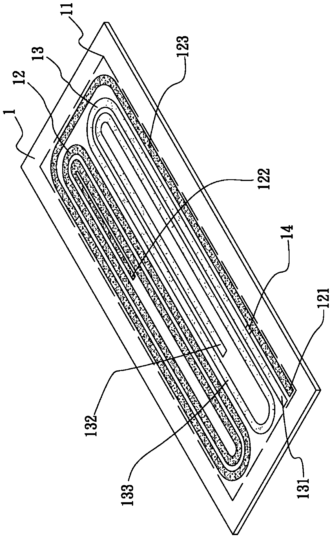
[0049] see figure 1 , 2 , is a perspective view and a top view of the first embodiment of the multi-frequency antenna structure of the present invention, as shown in the figure, the multi-frequency antenna structure of the present invention includes: a base 1;

[0050] One side of the base 1 has a first wiring area 11, the first wiring area 11 has a first metal wir...


PUM


Abstract

A multiband antenna structure comprises a base portion, one side of the base portion has a first wiring area, the first wiring area has a first metal wiring, a second metal wiring and a connection portion, the first and second metal wirings are arranged in a long-scrolling graph, and two ends of the connection portion are respectively electrically connected with the first and second metal wirings.The multiband antenna structure can achieve integration of the multiband antenna and the circuit to reduce the production cost and achieve the purpose of emitting or receiving multiband signals.

Description

technical field [0001] The invention relates to a multi-frequency antenna structure, in particular to a stable multi-frequency antenna structure which integrates the multi-frequency antenna directly with a circuit to save manufacturing cost and receive or transmit signals. Background technique [0002] At present, when the existing multi-frequency antenna is manufactured, multiple antennas are stamped and formed by metal sheets, and then bent into antennas, and then the multiple antennas that have been bent and formed are electrically connected to a single circuit substrate, so that the multiple antennas Antennas form a multi-band antenna structure arranged in a dual-polarized array, or the pattern of the antenna is printed on the copper film of the circuit substrate by printing technology, and then the pattern of the antenna is made by developing, exposing or etching techniques, and the multi-band Several circuit substrates with antenna patterns are stacked to form a multi-...

Claims


Application Information

Patent Timeline
Patent Type & Authority Applications(China)
IPC IPC(8): H01Q1/38H01Q5/28H01Q5/307
CPCH01Q1/38H01Q5/28H01Q5/307
Inventor 邱伯韦梁仰德许升睿林韦丞曾士修萧建仁
Owner KEYCORE TECH CORP
Why Eureka
Try Eureka