
Detection method of infrared scattering device and mobile terminal

An infrared scattering and mobile terminal technology, which is applied in the direction of measuring devices, machine/structural component testing, optical instrument testing, etc., can solve problems such as user injury, falling off or breaking, and judging infrared scattering devices, so as to avoid cost investment and reduce effect of complexity

Active Publication Date: 2018-12-07
VIVO MOBILE COMM CO LTD
View PDF9 Cites 2 Cited by
  • Summary
  • Abstract
  • Description
  • Claims
  • Application Information

AI Technical Summary

Problems solved by technology

[0003] The above-mentioned infrared scattering device is usually fixed in the mobile terminal by glue, and the material of the infrared scattering device is fragile, and may fall off or break under the action of an external force. Once the infrared scattering device works Abnormally, the infrared beam with high energy density emitted by the infrared laser device will be emitted directly, which may cause damage to the user (such as eyes, skin, etc.)
Since infrared light is invisible light, and the infrared scattering device is located inside the mobile terminal, it is difficult for users to judge whether the infrared scattering device is working normally by naked eyes, and it can only be detected by professionals

Method used


Image

  • Detection method of infrared scattering device and mobile terminal
  • Detection method of infrared scattering device and mobile terminal
  • Detection method of infrared scattering device and mobile terminal

Examples


Embodiment Construction

[0016] The following will clearly and completely describe the technical solutions in the embodiments of the present invention with reference to the accompanying drawings in the embodiments of the present invention. Obviously, the described embodiments are some of the embodiments of the present invention, but not all of them. Based on the embodiments of the present invention, all other embodiments obtained by persons of ordinary skill in the art without creative efforts fall within the protection scope of the present invention.

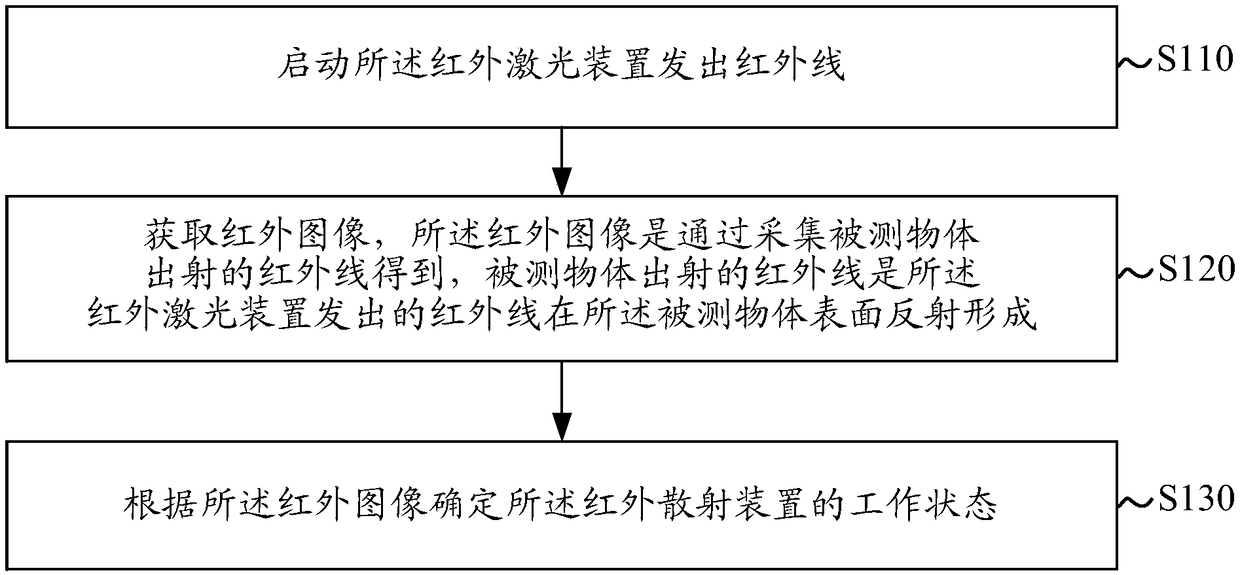
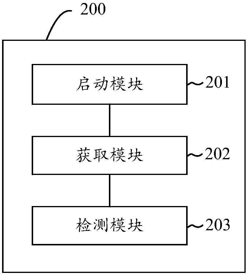
[0017] Such as figure 1 As shown, an embodiment of the present invention provides a method for detecting an infrared scattering device, which can be applied to a mobile terminal including an infrared laser device and an infrared scattering device, and the method includes the following steps:

[0018] S110: Start the infrared laser device to emit infrared rays.

[0019] In this embodiment, the infrared laser device can be started specifically by starti...


PUM


Abstract

The present invention discloses a detection method of an infrared scattering device and a mobile terminal which can rapidly and conveniently determine the work state of an infrared scattering device.The method is applied to the mobile terminal. The mobile terminal comprises an infrared laser device and an infrared scattering device. The method comprises the steps of: starting an infrared laser device to emit an infrared ray; obtaining an infrared image, wherein the infrared image is obtained by collecting the infrared ray emitted by a detected object, and the infrared ray emitted by the detected object is formed by reflecting the infrared ray emitted by the infrared laser device at the surface of the detected surface; and determining the work state of the infrared scattering device according to the infrared image, wherein the work state comprises normal work and abnormal work.

Description

technical field [0001] The invention relates to the field of terminals, in particular to a detection method of an infrared scattering device and a mobile terminal. Background technique [0002] With the development of mobile terminal technology, infrared laser devices are increasingly used in mobile terminals, so as to realize functions such as 3D face recognition or beautification blurring of mobile terminals. The front of the infrared laser device is usually equipped with an infrared scattering device, which is used to diffuse the high-energy-density infrared beam emitted by the infrared laser device into a uniform spot of low energy density or a special pattern of speckle before exiting. [0003] The above-mentioned infrared scattering device is usually fixed in the mobile terminal by glue, and the material of the infrared scattering device is fragile, and may fall off or break under the action of an external force. Once the infrared scattering device works Abnormally, t...

Claims


Application Information

Patent Timeline
Patent Type & Authority Applications(China)
IPC IPC(8): G01M11/00
CPCG01M11/00
Inventor 王智鹏
Owner VIVO MOBILE COMM CO LTD
Learn More