
Interlayer air supply air circulation system

An air circulation system and interlayer technology, which is applied in the field of interlayer air supply air circulation system, can solve the problems of large air volume and difficult control of temperature and humidity field uniformity, and achieve the effect of uniformity control

Inactive Publication Date: 2018-12-07
苏州美高图环境技术有限公司
View PDF6 Cites 2 Cited by
  • Summary
  • Abstract
  • Description
  • Claims
  • Application Information

AI Technical Summary

Problems solved by technology

[0002] Air treatment systems are widely used in households and industries. After the traditional air treatment system handles the temperature and humidity of the air, it is directly blown into the room through the fan unit for air circulation. There are often places close to the air outlet of the air treatment system where the air volume is relatively low. Large, but the air volume far away from the air outlet is small, and the uniformity of the temperature and humidity field is not easy to control

Method used


Image

  • Interlayer air supply air circulation system
  • Interlayer air supply air circulation system
  • Interlayer air supply air circulation system

Examples


Embodiment 1

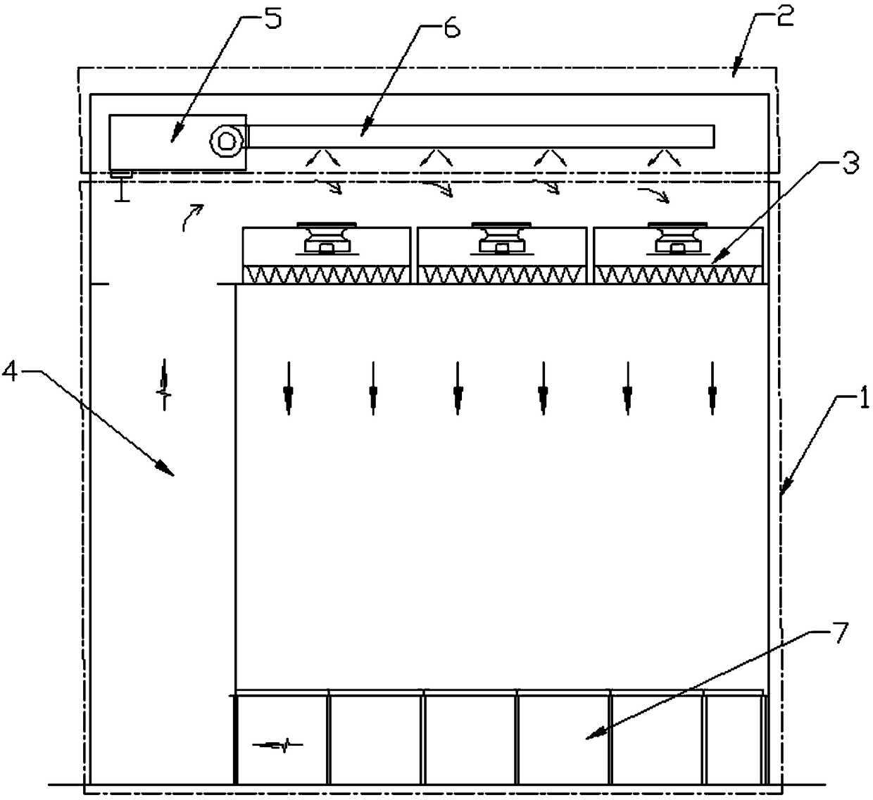
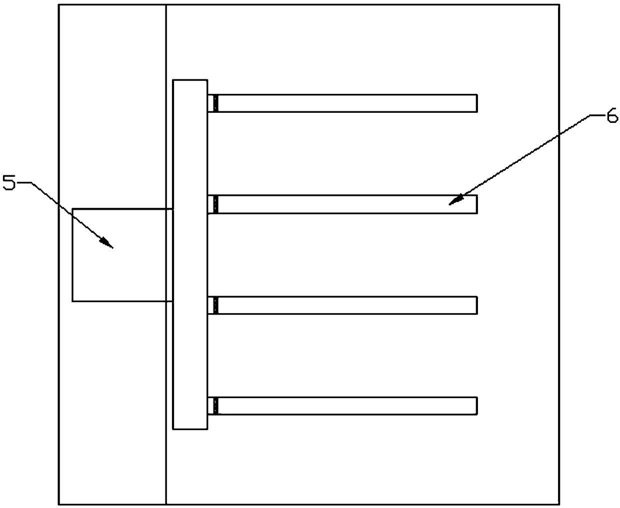
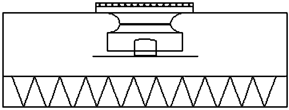
[0021] to combine Figure 1-4 , the interlayer air supply air circulation system of the present invention includes a large circulation unit 1 and a small circulation unit 2; the large circulation unit 1 includes several fan assemblies 3 and return air sandwich passages 4; the fan assemblies 3 are evenly installed on the upper part of the room; The circulation unit 2 includes several air supply pipes 6 and an air treatment device 5 connected to the air supply pipes 6; the air supply pipes 6 are uniformly arranged above the fan assembly 3, and a gap is provided between the air supply pipe 6 and the fan assembly 3, Form the air supply static pressure layer. The air treatment device 5 can be installed indoors or outdoors, and the air is sent into the air supply pipe 6 after the air is processed. The return air duct 4 can be installed on one side wall, two sides wall or surrounding walls, and the quantity can be selected by oneself.

[0022] In addition, the large circulation uni...

Embodiment 2

[0026] combined with Figure 5 , another embodiment of the present invention, the interlayer air supply air circulation system, includes a large circulation unit 1 and a small circulation unit 2; the large circulation unit 1 includes several fan assemblies 3 and return air passages 4; the fan assemblies 3 are uniform Installed on the upper part of the room; the small circulation unit 2 includes several air supply pipes 6 and the air treatment device 5 connected to the air supply pipes 6; the air supply pipes 6 are evenly arranged above the fan assembly 3, and There is a gap between them to form a static pressure layer for air supply. The air treatment device 5 can be installed indoors or outdoors, and the air is sent into the air supply pipe 6 after the air is processed. Others are consistent with Example 1.

[0027] In this embodiment, the air supply pipe is arranged under the air supply static pressure layer of the large circulation air, and the large circulation air circu...


PUM


Abstract

The invention discloses an interlayer air supply air circulation system, and belongs to the technical field of air conditioning systems. The interlayer air supply air circulation system comprises a large circulation unit and a small circulation unit; the large circulation unit comprises a plurality of fan assemblies and an air return duct; the fan assemblies are uniformly installed on the upper part of the room; the small circulation unit comprises a plurality of air supply pipes and an air processing device connected with the air supply pipes; the air supply pipes are uniformly arranged abovethe fan assemblies, and a gap is formed between the air supply pipes and the fan assemblies, an air supply static pressure layer is formed between the air supply pipes and the fan assemblies. The interlayer air supply air circulation system adopts a mode of combining large circulation and small circulation, so that the uniformity of the indoor temperature and humidity field is controlled.

Description

technical field [0001] The invention relates to an interlayer air supply air circulation system, which belongs to the technical field of air conditioning systems. Background technique [0002] Air treatment systems are widely used in households and industries. After the traditional air treatment system handles the temperature and humidity of the air, it is directly blown into the room through the fan unit for air circulation. There are often places close to the air outlet of the air treatment system where the air volume is relatively low. Large, while the air volume far away from the air outlet is small, and the uniformity of the temperature and humidity field is not easy to control. Contents of the invention [0003] In order to solve the above problems, the present invention provides a interlayer air supply air circulation system. The interlayer air supply air circulation system of the present invention adopts a combination of large circulation and small circulation. The...

Claims


Application Information

Patent Timeline
Patent Type & Authority Applications(China)
IPC IPC(8): F24F7/10F24F13/02F24F13/068
CPCF24F7/10F24F13/0227F24F13/068
Inventor 王学平
Owner 苏州美高图环境技术有限公司
Learn More