Channel device for controlling magnetic liquid metal by utilizing electromagnetic field coupling

A liquid metal, coupled control technology, applied in magnetic liquids, magnetic objects, circuits, etc., can solve problems such as rare research on magnetic liquid metals

Active Publication Date: 2018-12-07
SUZHOU UNIV
View PDF5 Cites 1 Cited by
  • Summary
  • Abstract
  • Description
  • Claims
  • Application Information

AI Technical Summary

Problems solved by technology

[0002] The electric field is the main way to drive liquid metal, but it is not yet mature for multiple circuits to drive liquid metal at the same time; in addition, in the multi-channel with intersection points, the magnetic liquid metal will only stop at the multi-channel intersection point and cannot continue to move forward; finally, Both magnetic and electric fields can drive magnetic liquid metals, but there are few studies on the simultaneous control of magnetic liquid metals by both methods

Method used


Image

  • Channel device for controlling magnetic liquid metal by utilizing electromagnetic field coupling
  • Channel device for controlling magnetic liquid metal by utilizing electromagnetic field coupling
  • Channel device for controlling magnetic liquid metal by utilizing electromagnetic field coupling

Examples


Embodiment 1

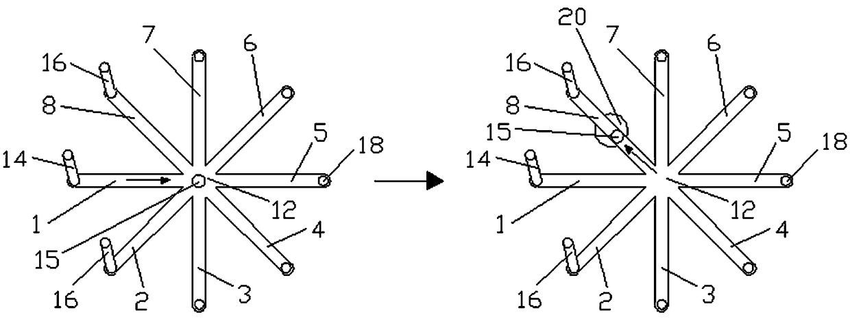
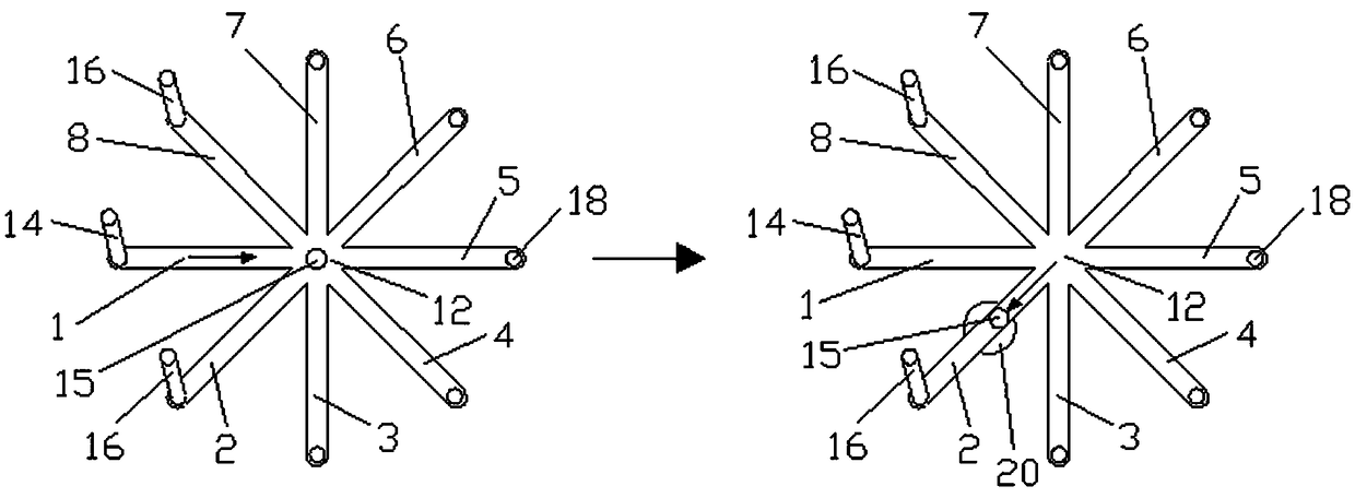
[0025] Such as figure 1 , figure 2 As shown, the channel device of magnetic liquid metal controlled by electromagnetic field coupling includes a power supply (not shown in the figure), a magnetic field element and eight channels. The power supply is used to form an electric field, and the magnetic field element is used to form a magnetic field. The eight channels are the first One channel 1, the second channel 2, the third channel 3, the fourth channel 4, the fifth channel 5, the sixth channel 6, the seventh channel 7 and the eighth channel 8, the first channel 1, the second channel 2, the The three passages 3, the fourth passage 4, the fifth passage 5, the sixth passage 6, the seventh passage 7 and the eighth passage 8 all intersect at a bifurcation 12, and the first passage 1, the second passage 2, and the third passage 3 , the fourth channel 4, the fifth channel 5, the sixth channel 6, the seventh channel 7 and the eighth channel 8 and the bifurcation 12 are all provided ...

Embodiment 2

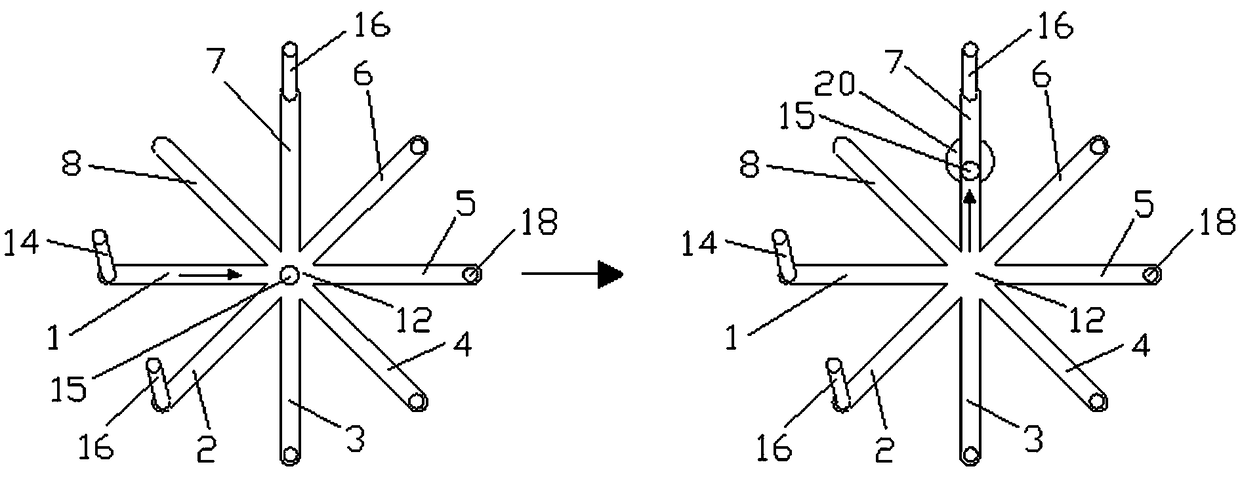
[0034] Such as image 3 As shown, the difference between the second embodiment and the first embodiment is that the second electrode 16 arranged in the eighth channel 8 is changed to be arranged in the seventh channel 7, and the distance between the second channel 2 and the seventh channel 7 is 135 °, under the action of the magnet 20, the magnetic liquid metal 15 can advance along the seventh channel 7.

Embodiment 3

[0036] Such as Figure 4 As shown, the difference between the third embodiment and the first embodiment is that the second electrode 16 arranged in the eighth channel 8 is changed to be arranged in the sixth channel 6, and the distance between the second channel 2 and the sixth channel 6 is 180 °, under the action of the magnet 20, the magnetic liquid metal 15 can advance along the sixth channel 6.


PUM


Abstract

The invention relates to a channel device for controlling magnetic liquid metal by utilizing electromagnetic field coupling. The channel device comprises a power supply, a magnetic field element and aplurality of channels, wherein the channels are crossed at a branch; an electrolyte solution is arranged in each channel and the branch; a first electrode is arranged in one channel, and second electrodes are arranged in the rest of at least two channels; the first electrode is connected with a negative electrode of the power supply; each second electrode is connected with the positive electrodeof the power supply; when at least two positive electrode circuits are accessed, magnetic liquid metal moves to stop at the branch; after the magnetic field element gets close to the liquid metal, andthe magnetic liquid metal is attracted to an inlet of certain channel, the magnetic field element is removed, and under action of the electric fields, the magnetic liquid metal moves forwards along the channel. Magnetic fields are utilized for assisting magnetic liquid metal to move in the electric fields, and magnetic fields are applied to the bottoms of the channels, so that the magnetic liquidmetal smoothly moves in the target channel.

Description

technical field [0001] The invention relates to a liquid metal, in particular to a channel device for controlling magnetic liquid metal by electromagnetic field coupling. Background technique [0002] The electric field is the main way to drive liquid metal, but it is not yet mature for multiple circuits to drive liquid metal at the same time; in addition, in the multi-channel with intersection points, the magnetic liquid metal will only stop at the multi-channel intersection point and cannot continue to move forward; finally, Both magnetic and electric fields can drive magnetic liquid metals, but there are few studies on the simultaneous control of magnetic liquid metals in both ways. Contents of the invention [0003] The invention overcomes the deficiencies of the prior art and provides a channel device for controlling magnetic liquid metal by means of electromagnetic field coupling. [0004] In order to achieve the above object, the technical solution adopted by the p...

Claims


Application Information

Patent Timeline
IPC IPC(8): F17D1/08H01F1/44H01F7/00H01F7/02
CPCF17D1/08H01F1/44H01F7/00H01F7/02
Inventor 李芳霞谢杰刘马泽杨浩匡绍龙李相鹏孙立宁
Owner SUZHOU UNIV
Why Eureka
Try Eureka