
Mule spinning machine

The invention relates to a spinning frame and frame technology, which is applied to a walking frame spinning frame. field, it can solve the problems of high labor intensity, difficult operation, heavy weight, etc., and achieve the effect of reducing labor intensity and convenient operation

Pending Publication Date: 2018-12-07
浙江绿洲纺织股份有限公司
View PDF9 Cites 1 Cited by
  • Summary
  • Abstract
  • Description
  • Claims
  • Application Information

AI Technical Summary

Problems solved by technology

[0004] However, the yarn feeding mechanism on the above-mentioned vertical spinning frame still has the following problems in use: when the bobbin is placed on the bobbin frame, due to the heavy weight of the bobbin, it is difficult to move the bobbin to the bobbin frame. When the operation is not easy, the labor intensity is high

Method used

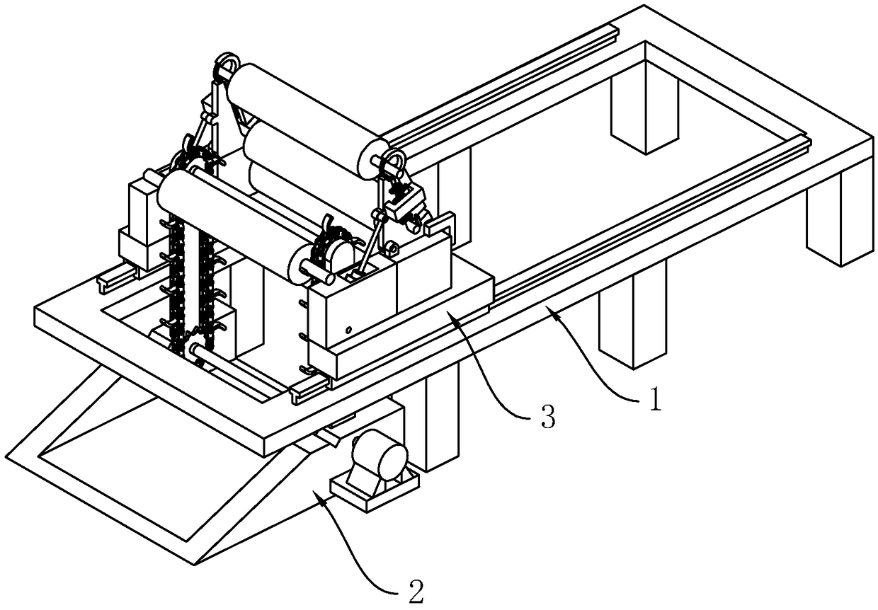

Image

  • Mule spinning machine
  • Mule spinning machine
  • Mule spinning machine

Examples


Embodiment

[0035] Embodiment: a kind of walking frame spinning machine, combines figure 1 , including a frame 1, one end of the frame 1 is fixedly connected with a lifting component 2, and a walking frame 3 is slidably connected with the frame 1.

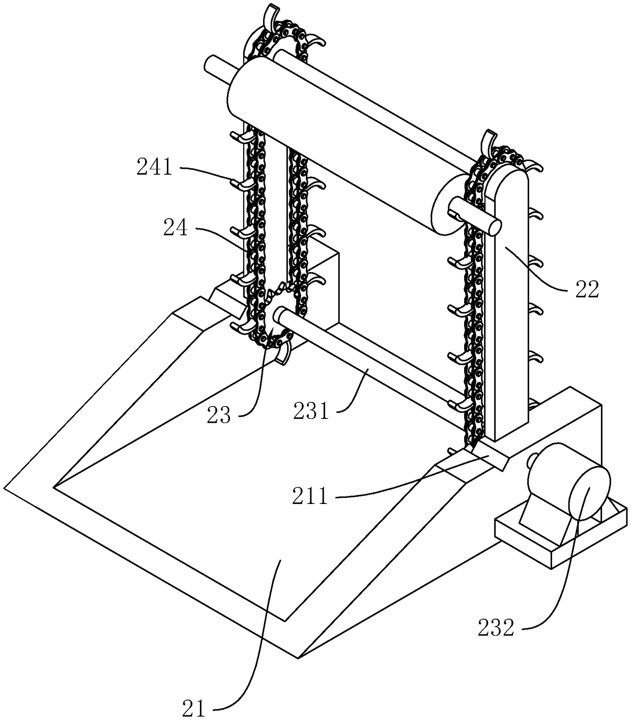
[0036] combine figure 2 The lifting assembly 2 includes a base 21, the length direction of the base 21 is the same as the length direction of the walking frame 3, the two ends of the base 21 are vertically fixedly connected with two vertical plates 22, and the sides of the two vertical plates 22 that are close to each other are respectively rotatably connected with Two vertically arranged sprockets 23, the axes of the sprockets 23 are all set horizontally, and the axes of the sprockets 23 of the two vertical plates 22 are all in the same vertical plane, and the lower side sprockets 23 of the two vertical plates 22 are fixedly connected with Transmission shaft 231, the lower end sprocket wheel 23 of one side vertical plate 22 is also provided...


PUM


Abstract

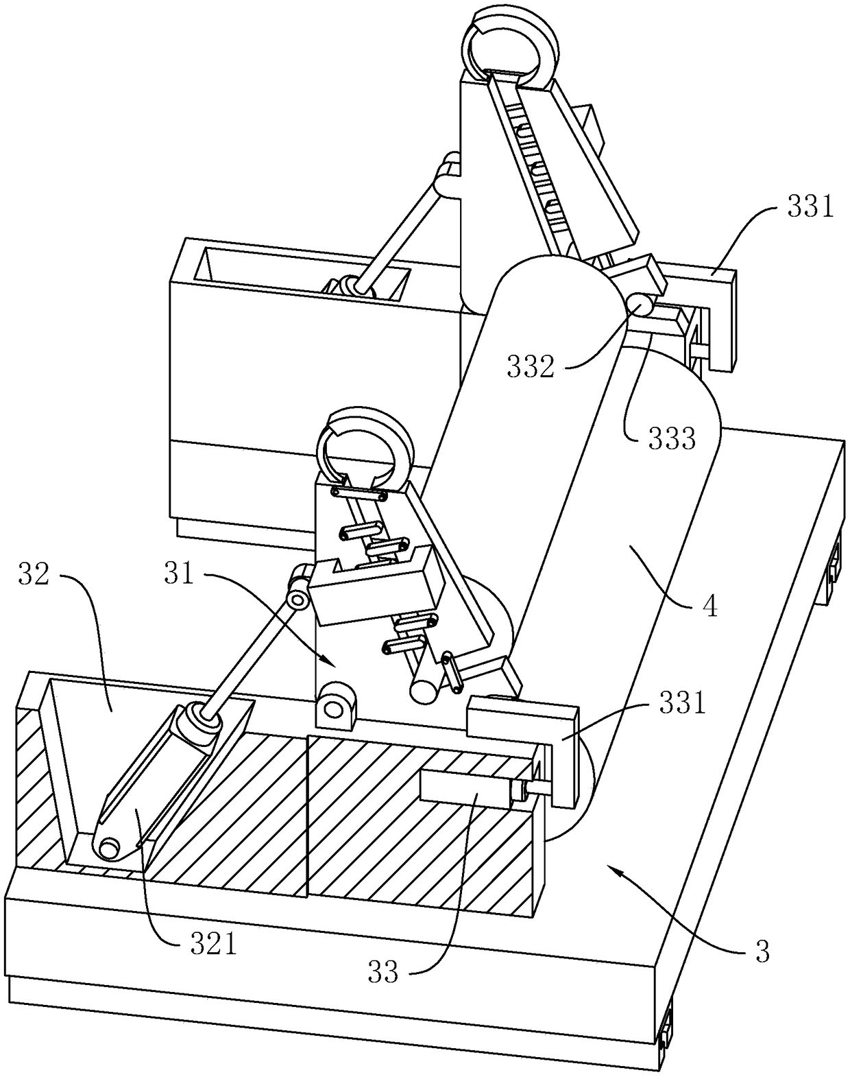
The invention discloses a mule spinning machine, and relates to the field of spinning machines. The mule spinning machine comprises a machine frame and a mule slidingly connected to the machine frame,two yarn roller racks are rotatably connected to the two ends of the mule respectively, fixing arms are fixedly connected to the upper ends of the two yarn roller racks respectively and slidingly connected with movable arms, inserting grooves are formed in the upper ends of the yarn roller racks, pushing springs are further arranged on the fixing arms and can push the movable arms to be insertedinto the inserting grooves, a lifting assembly is arranged at one end of the machine frame, a first driving mechanism capable of driving the two yarn roller racks to rotate is arranged on the mule, and arc surfaces are further arranged on the outer sides of the movable arms, and can slide the movable arms when the movable arms abut against the ends of yarn rollers, so that the ends of the yarn rollers are inserted into supporting rings. The problems are solved that in the prior art, when yarn rollers are carried onto a reel rack, operation is difficult, and labor intensity is high, and the mule spinning machine has the advantages that the yarn rollers can be conveniently placed on the reel rack, operation is simple, and the labor intensity is lowered.

Description

technical field [0001] The invention belongs to the field of spinning machines, in particular to a frame spinning machine. Background technique [0002] The spinning process of processing wool fibers into yarns is called wool spinning. Wool fibers are mainly wool, and also include animal hairs such as cashmere and rabbit hair. Clothes made of wool fabrics feel soft and moist. In the spinning process, the task of the woolen spinning process: the sliver sliver from the woolen carding machine will be directly taken to the woolen spinning machine after drafting and twisting, and spun into a spun yarn with uniform dryness, certain linear density and strength, and then Winding into a certain shape for use in the next process. Slubbing spinning frame can be divided into two categories: one is discontinuous spinning frame, usually spindle type (including frame type) spinning frame; the other is continuous spinning frame, often ring spinning machine. Among them, the walking frame ...

Claims


Application Information

Patent Timeline
IPC IPC(8): D01H3/06
CPCD01H3/06
Inventor 杨铁峰林通
Owner 浙江绿洲纺织股份有限公司
Learn More