Mechanical shaft part quenching device

A technology of quenching device and mechanical shaft, applied in the direction of quenching device, furnace, heat treatment equipment, etc., can solve the problems of slow start, difficult operation, complex structure, etc., and achieve the effect of increasing the quantity and improving the efficiency of processing

Inactive Publication Date: 2018-12-07
詹应博
View PDF5 Cites 0 Cited by
  • Summary
  • Abstract
  • Description
  • Claims
  • Application Information

AI Technical Summary

Problems solved by technology

[0003] The purpose of the present invention is to provide a quenching device for mechanical shaft parts in order to solve the above problems, which solves the shortcomings of the existing quenching device such as complex structure, difficult operation, slow start and low processing efficiency.

Method used


Image

  • Mechanical shaft part quenching device
  • Mechanical shaft part quenching device
  • Mechanical shaft part quenching device

Examples


Embodiment Construction

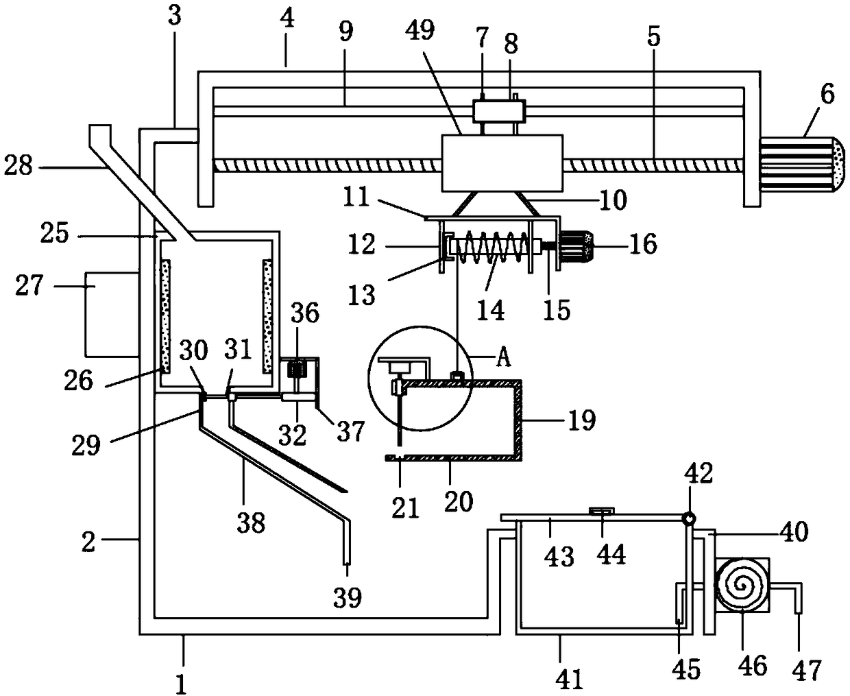
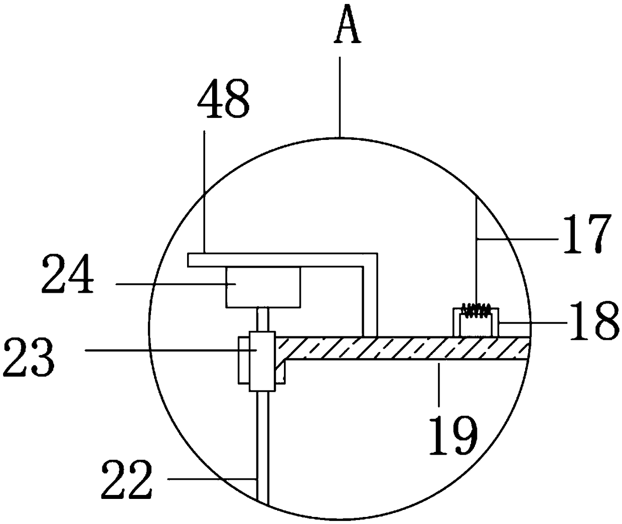
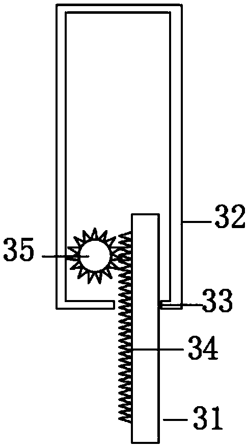
[0020] Such as Figure 1-3 As shown, this specific embodiment adopts the following technical solutions: a quenching device for mechanical shaft parts, including a base plate 1, a support rod 2 is fixedly connected above the base plate 1, and a crossbeam is fixedly connected to the upper side of the support rod 2 3. The base plate 1 is fixedly connected to the beam 3 through the support rod 2, a C-shaped mounting plate 4 is fixedly connected to one side of the beam 3, and a screw rod 5 is rotatably connected between the C-shaped mounting plates 4. One end of the screw mandrel 5 is connected with a screw motor 6, and the screw motor 6 is installed on the outside of the C-shaped mounting plate 4. The screw rod 5 is threaded with a moving sleeve rod 49, and the upper side of the moving sleeve rod 49 is fixedly connected with a A plurality of guide plates 7, guide rings 8 are fixedly interspersed between the guide plates 7, guide rods 9 are slidably interspersed on the guide rings ...


PUM


Abstract

The invention discloses a mechanical shaft part quenching device. The mechanical shaft part quenching device comprises a base plate, wherein a supporting rod is fixedly connected above the base plate,a cross beam is fixedly connected to one side above the supporting rod, the base plate is fixedly connected with the cross beam through the supporting rod, a C-shaped mounting plate is fixedly connected to one side of the cross beam, and a screw rod is rotationally connected to the two sides of the C-shaped mounting plate. According to the mechanical shaft part quenching device, a first heat preservation box is arranged, a heated mechanical shaft part can be conveyed to the first heat preservation box through a first feeding port, a first heater is used for enabling an internal temperature ofthe first heat preservation box to be high, a cooling box is driven to move rightwards through a screw rod motor to a position above a cooling pond filled with cooling water in advance, then the cooling box is lowered to be completely immersed in the cooling pond, so that the mechanical shaft part in the cooling box is quenched, the number of the mechanical shaft parts quenched one time can be increased through the design, and the processing efficiency is greatly improved.

Description

Technical field: [0001] The invention belongs to the technical field of quenching devices, in particular to a quenching device for mechanical shaft parts. Background technique: [0002] In the prior art, most of the traditional quenching devices use fixtures such as manipulators to manually clamp the parts into the cooling pool for quenching. This method is not efficient, and the parts are not easy to maintain high temperature during the clamping process, which is easy to affect the quenching process. success rate, so the present invention proposes a quenching device for mechanical shaft parts. Invention content: [0003] The purpose of the present invention is to provide a quenching device for mechanical shaft parts in order to solve the above problems, which solves the disadvantages of the existing quenching device such as complex structure, difficult operation, slow operation and low processing efficiency. [0004] In order to solve the above problems, the present inve...

Claims


Application Information

Patent Timeline
Patent Type & Authority Applications(China)
IPC IPC(8): C21D9/28C21D1/63
CPCC21D9/28C21D1/63
Inventor 詹应博
Owner 詹应博
Why Eureka
Try Eureka