
Turnover device for electromechanical device installation

A technology of turning device and electromechanical equipment, which is applied in the direction of hoisting device, hoisting device, conveyor objects, etc., which can solve the problems of turning the turning device quickly, inconvenient to fix and protect, not stable and reliable enough, and achieve the effect of stable and reliable turning

Inactive Publication Date: 2018-12-07
JIUJIANG VOCATIONAL & TECHN COLLEGE
View PDF5 Cites 3 Cited by
  • Summary
  • Abstract
  • Description
  • Claims
  • Application Information

AI Technical Summary

Problems solved by technology

With the rapid development and wide application of computer technology, mechatronics technology has achieved unprecedented development. Electromechanical installation includes the installation of equipment, electrical appliances, lines, and pipelines for engineering construction projects. When installing electromechanical, it is often necessary to install some large electromechanical Due to the weight of the equipment and the large size of the equipment, it needs to be hoisted by ropes, etc., then manually turned over, and then moved to the designated installation position to achieve the predetermined installation position, but this requires a lot of peripheral equipment, and Manual flipping is dangerous, so people have designed a flipping device to flip the electromechanical equipment by 90 degrees to adjust the installation state. After placement, it is inconvenient to carry out fixed protection, and it is easy to cause accidents of electromechanical equipment slipping during the overturning process, and the overturning device itself has a certain height, and placing the equipment on the device requires a certain amount of manual assistance, so it is not easy to enter and exit the material

Method used


Image

  • Turnover device for electromechanical device installation
  • Turnover device for electromechanical device installation
  • Turnover device for electromechanical device installation

Examples


Embodiment Construction

[0024] The following will clearly and completely describe the technical solutions in the embodiments of the present invention with reference to the accompanying drawings in the embodiments of the present invention. Obviously, the described embodiments are only some, not all, embodiments of the present invention. Based on the embodiments of the present invention, all other embodiments obtained by persons of ordinary skill in the art without making creative efforts belong to the protection scope of the present invention.

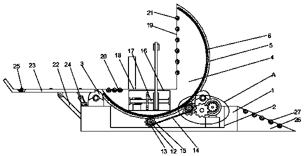
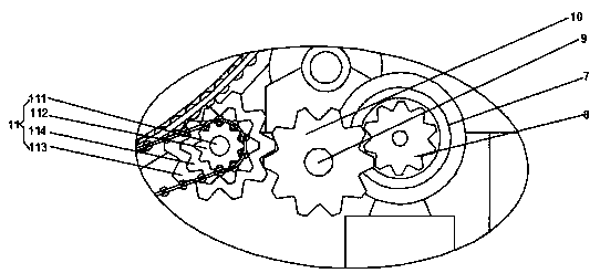
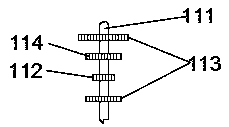
[0025] see Figure 1-6, the present invention provides a technical solution: a turning device for electromechanical equipment installation, including a fixed base 1, a control groove 2 is opened on the top of the fixed base 1, and the positions on both sides of the control groove 2 at the top of the fixed base 1 are connected through the rotation of the mounting base There is a support pulley 3, and the upper side of the fixed base 1 is provided with an overtu...


PUM


Abstract

The invention discloses a turnover device for electromechanical device installation. The turnover device comprises a fixed base, a control groove is formed in the top of the fixed base, supporting sliding wheels are rotationally connected to the positions, on the two sides of the control groove, at the top of the fixed base through installing bases, a turnover base is arranged on the upper side ofthe fixed base, sliding rails are fixedly connected to the outer surface of the turnover base, the sides, far away from the turnover base, of the outer walls of the sliding rails are connected with the sliding outer surfaces of the supporting sliding wheels, a turnover chain is fixedly connected to the outer side of the turnover base, a turnover motor is fixedly connected to the bottom of the inner wall of the control groove through a motor base, the front side of the turnover motor is rotationally connected with a first driving gear through an output shaft, a connecting shaft is rotationallyconnected to the two sides of the inner wall of the control groove, and a first reduction gear is fixedly connected to the outer surface of the connecting shaft. The turnover device for electromechanical device installation is relatively stable and reliable in turnover and convenient to protect, prevents sliding of electromechanical devices, and facilitates feeding and discharging.

Description

technical field [0001] The invention relates to the technical field of electromechanical equipment, in particular to a turning device for installing electromechanical equipment. Background technique [0002] Mechatronics is the interdisciplinary integration of machinery, electronics, optics, control, computer, information and other disciplines. Its development and progress rely on and promote the development and progress of related technologies, combining the application of mechanical technology and electronic technology. With the rapid development and wide application of computer technology, mechatronics technology has achieved unprecedented development. Electromechanical installation includes the installation of equipment, electrical appliances, lines, and pipelines for engineering construction projects. When installing electromechanical, it is often necessary to install some large electromechanical Due to the weight of the equipment and the large size of the equipment, it...

Claims


Application Information

Patent Timeline
IPC IPC(8): B65G47/248B66F19/00
CPCB65G47/248B66F19/00
Inventor 段慧云汪洋青夏志平
Owner JIUJIANG VOCATIONAL & TECHN COLLEGE
Learn More