
Odor generating device and virtual olfactory system

An odor generation and odor technology, applied in general control systems, control/regulation systems, simulators, etc., can solve the problem of insufficient odor immediacy, and achieve the effect of fast odor generation and improved accuracy

Active Publication Date: 2018-12-07
GUANGDONG UNIV OF TECH
View PDF6 Cites 8 Cited by
  • Summary
  • Abstract
  • Description
  • Claims
  • Application Information

AI Technical Summary

Problems solved by technology

[0003] Aiming at the deficiencies of the prior art, the present invention proposes a virtual olfactory device and system, which solves the problem of insufficient immediacy of odor generation in the prior art

Method used


Image

  • Odor generating device and virtual olfactory system
  • Odor generating device and virtual olfactory system
  • Odor generating device and virtual olfactory system

Examples


Embodiment 1

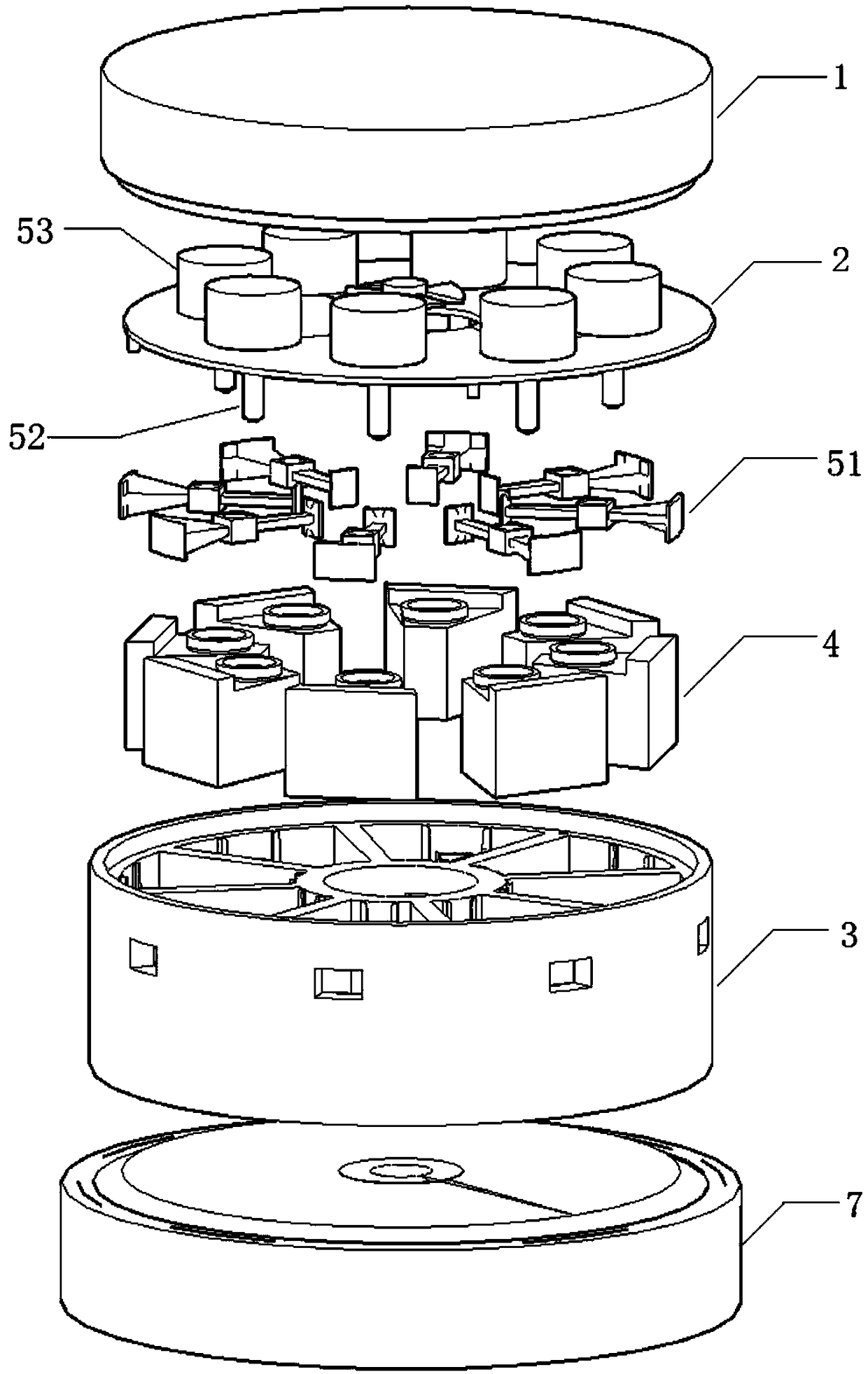
[0033] Example 1, see Figure 1-7 :

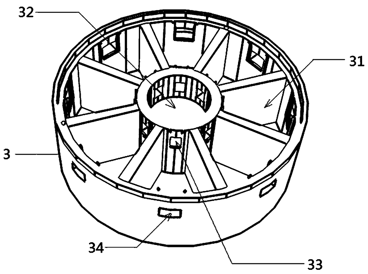
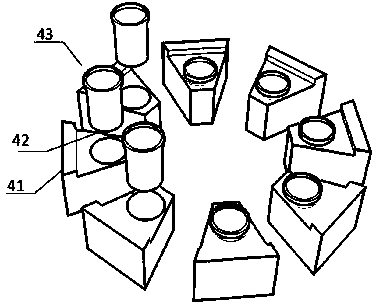
[0034] An odor generating device, comprising a housing, including a main structure 3 with an open upper end and a cover plate 2 for covering the opening of the main structure 3, the main structure 3 is divided into a plurality of box slots 31 and a channel 32, The channel 32 is located in the middle of the main structure 1, and a plurality of box-setting slots 31 are arranged around the channel 32. Adjacent box-setting slots 31 are separated from each other by side slot walls, and each box-setting slot 31 is separated from the channel 32 by the inner slot wall. , the inner groove wall of each box slot 31 is provided with an air inlet 33, each box slot 31 and the shared outer wall of the main structure 3 are provided with an air outlet 34, and the number of the air outlet 34 is related to the number of air outlets. The number of box slots 31 is the same, and one box slot 31 corresponds to one air outlet 34 . The middle of the cover plate ...

Embodiment 2

[0047] Example 2, see Figure 8 :

[0048] A virtual olfactory system, comprising the above-mentioned odor generating device and a host computer, the host computer and the odor generating device are connected in communication, and the host computer sends an odor generating request to the odor generating device according to the received scene identification, and the gas generating request includes a predetermined gas number, odor The lower computer of the generating device receives the smell request, and the control device generates the smell corresponding to the scene identification. In this embodiment, the upper computer is a host computer, and the lower computer is a single-chip microcomputer control module. Among them, the upper and lower computers communicate through the WiFi module, and the WIFI module is designed on the lower computer to receive the data transmitted from the upper computer. The WiFi module is a communication module between the computer host and the singl...


PUM


Abstract

The invention provides an odor generating device and a virtual olfactory system. The odor generating device comprises a shell, an odor generating component and an odor sending module, wherein the shell comprises a main structure and a cover plate; a channel is arranged in the middle of the main structure; more than two box storage slots are formed around the channel; an air inlet and an air outletare formed on each of the box storage slots; the odor generating component comprises an odor box and an atomizing sheet; the odor box is used for carrying the liquid capable of generating a specificodor; the atomizing sheet is used for accelerating the atomization of the liquid; the odor sending module comprises an air blower and an airflow path. The odor generating device provided by the invention adopts the atomizing sheet for atomizing the liquid and utilizes the air blower to accelerate the odor spreading, so that the problem of insufficient instantaneity of odor generation of the priorart can be solved. The virtual olfactory system comprises the odor generating device and an upper computer. The upper computer is used for sending an odor generating request to the odor generating device according to a received scene identifier, so that the system can generate virtual odors corresponding to different scenes.

Description

technical field [0001] The invention relates to the technical field of gas generation, in particular to an odor generating device and a virtual olfactory system. Background technique [0002] Olfactory perception is one of the five major perceptions of human beings. In the field of virtual reality technology, the realization of virtual olfactory generation is an important research direction. Some of the existing odor generating devices use heating spice flakes to generate smell, and the process from heating spice flakes to odor generation takes a certain amount of time, and the immediacy is not enough; at the same time, overheated gas is unsafe to the human body, and the manufacturing process of spice flakes is complicated. , The types of spice tablets are limited, so that the applicable scenarios are limited. Contents of the invention [0003] Aiming at the deficiencies of the prior art, the present invention proposes a virtual olfactory device and system, which solves t...

Claims


Application Information

Patent Timeline
Patent Type & Authority Applications(China)
IPC IPC(8): A61L9/14G05B19/042
CPCA61L9/14G05B19/0423A61L2209/13A61L2209/111
Inventor 吴悦明陈友滨何汉武邹序焱许明西胡兆勇
Owner GUANGDONG UNIV OF TECH
Learn More