A continuous pollination device
A pollination device and connected technology, applied in the field of continuous pollination devices, can solve the problems of poor pollination effect, achieve the effects of improving utilization rate, increasing collection rate, and avoiding inactivation
- Summary
- Abstract
- Description
- Claims
- Application Information
AI Technical Summary
Problems solved by technology
Method used
Image

Examples
Embodiment 1
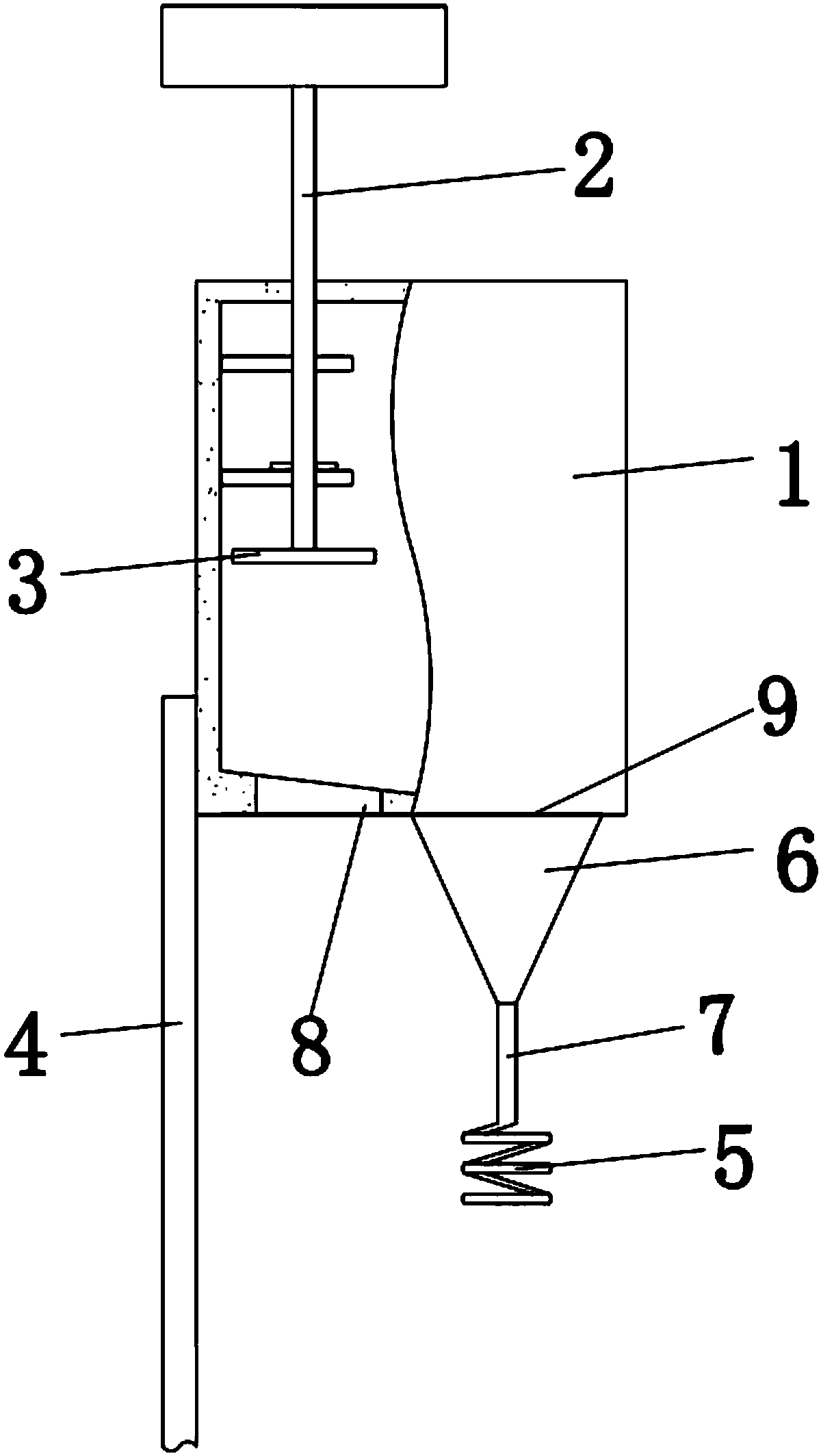
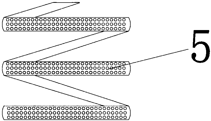
[0030] Such as figure 1 and figure 2 As shown, the continuous pollination device of the present embodiment includes a collector 1 and a solenoid 5, and the bottom of the collector 1 is provided with an ear inlet 8 and a pollination hole 9, and the pollination hole 9 is connected to the pollination hole 9. The solenoid 5 is connected, and the surface of the solenoid 5 is provided with a plurality of leakage holes; the connection between the powder discharge hole 9 and the solenoid 5 is sealed externally with an isolation bag, and the isolation An ear is placed under the solenoid 5 in the bag, and the stem of the ear is also sealed and socketed with the isolation belt, so as to realize the closed pollination of the ear.
[0031] The tassel enters the collector 1 from the ear inlet 8, and then the pollen of the tassel falls to the bottom of the collector 1 under external force such as artificial force, and then enters the solenoid 5 through the pollen discharge hole 9, so that ...
Embodiment 2
[0033] Such as figure 1 Shown, the continuous pollination device of the present embodiment, on the basis of embodiment 1,
[0034] The side of the collector 1 is provided with ventilation holes, and the ventilation holes can be covered with a breathable filter membrane, which can prevent the miscellaneous powder in the air from entering the collector 1, ensuring that there is no interference of miscellaneous powder from different plants during the collection process. In addition, the tassels can also be sealed through a breathable filter membrane to ensure the purity of the pollen during pollination.
[0035] The setting of the ventilation hole facilitates the entry of outside wind, realizes the balance control of the temperature and humidity of the pollen in the isolation zone, prevents the pollen from agglomerating and inactivating, and ensures the vitality of the pollen.
Embodiment 3
[0037] Such as figure 1 Shown, the continuous pollination device of the present embodiment, on the basis of embodiment 1 or 2,
[0038] Described collector 1 is provided with the device that can shake tassel; Described device that can shake tassel includes bar one 2, and one end of described bar one 2 is provided with driving lever 3, and described bar one 2 The other end is provided with fan blade.
[0039] The setting of the fan blade is to use the natural wind to blow the fan blade to drive the rotation of the rod 2 and the driving rod 3, and the driving rod 3 is in contact with the tassel, and the driving rod 3 will continuously hit the tassel, realizing the automatic continuous tapping of the driving rod The tassels promote the pollen drop of the tassels, which further increases the pollen collection rate of the tassels, and also facilitates automatic pollination.
PUM
 Abstract
Description
Claims
Application Information
 - R&D
- Intellectual Property
- Life Sciences
- Materials
- Tech Scout
- Unparalleled Data Quality
- Higher Quality Content
- 60% Fewer Hallucinations
Browse by: Latest US Patents, China's latest patents, Technical Efficacy Thesaurus, Application Domain, Technology Topic, Popular Technical Reports.
© 2025 PatSnap. All rights reserved.Legal|Privacy policy|Modern Slavery Act Transparency Statement|Sitemap|About US| Contact US: help@patsnap.com