
Camera fill light control circuit and control method thereof

A technology for controlling circuits and cameras, which is applied in the field of photography, and can solve problems such as flickering of supplementary lights and affecting the normal use of cameras, so as to achieve the effects of avoiding flickering, improving the quality of monitoring, and reducing power consumption

Pending Publication Date: 2018-12-04
深圳市威特迪科技有限公司
View PDF11 Cites 3 Cited by
  • Summary
  • Abstract
  • Description
  • Claims
  • Application Information

AI Technical Summary

Problems solved by technology

The utility model is provided with a photosensitive belt, which senses the intensity of the external light, and transmits the signal of the intensity of the external light back to the circuit board, so as to control the amount of the supplementary light to go out. However, the utility model has the supplementary light Stroboscopic problem: When the natural light becomes dark at night, the photosensitive belt senses the dimming of the external light, and the circuit board starts the supplementary light to supplement the light in the camera area. Once the supplementary light is turned on, the photosensitive belt senses the camera again The brightness of the area becomes stronger. At this time, the circuit board controls the fill light to turn off and stop the fill light. This repeatedly causes the fill light to flicker, which affects the normal use of the camera.
This utility model uses a controllable constant current source to control the volume of the supplementary light. The signal to control the switch light inevitably comes from the photosensitive sensor installed near the surveillance camera. In today's industry, the photosensitive sensor is usually installed at the end of the surveillance camera. During the installation process, keep the direction of the photosensitive sensor opposite to the direction of light emission of the supplementary light, but this installation method can only be applied to a relatively open outdoor environment. For small or dense monitoring areas, the reflection of the supplementary light The light will also affect the normal sensing of the photosensitive sensor, which will cause the fill light to flicker

Method used


Image

  • Camera fill light control circuit and control method thereof
  • Camera fill light control circuit and control method thereof
  • Camera fill light control circuit and control method thereof

Examples


Embodiment Construction

[0033] In order to make the object, technical solution and advantages of the present invention clearer, the present invention will be further described in detail below in conjunction with the accompanying drawings and embodiments. It should be understood that the specific embodiments described here are only used to explain the present invention, not to limit the present invention.

[0034] To achieve the above object, the technical scheme of the present invention is as follows:

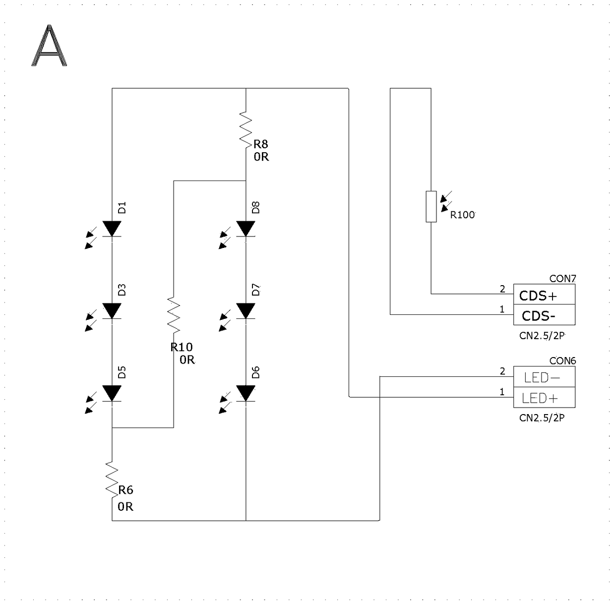
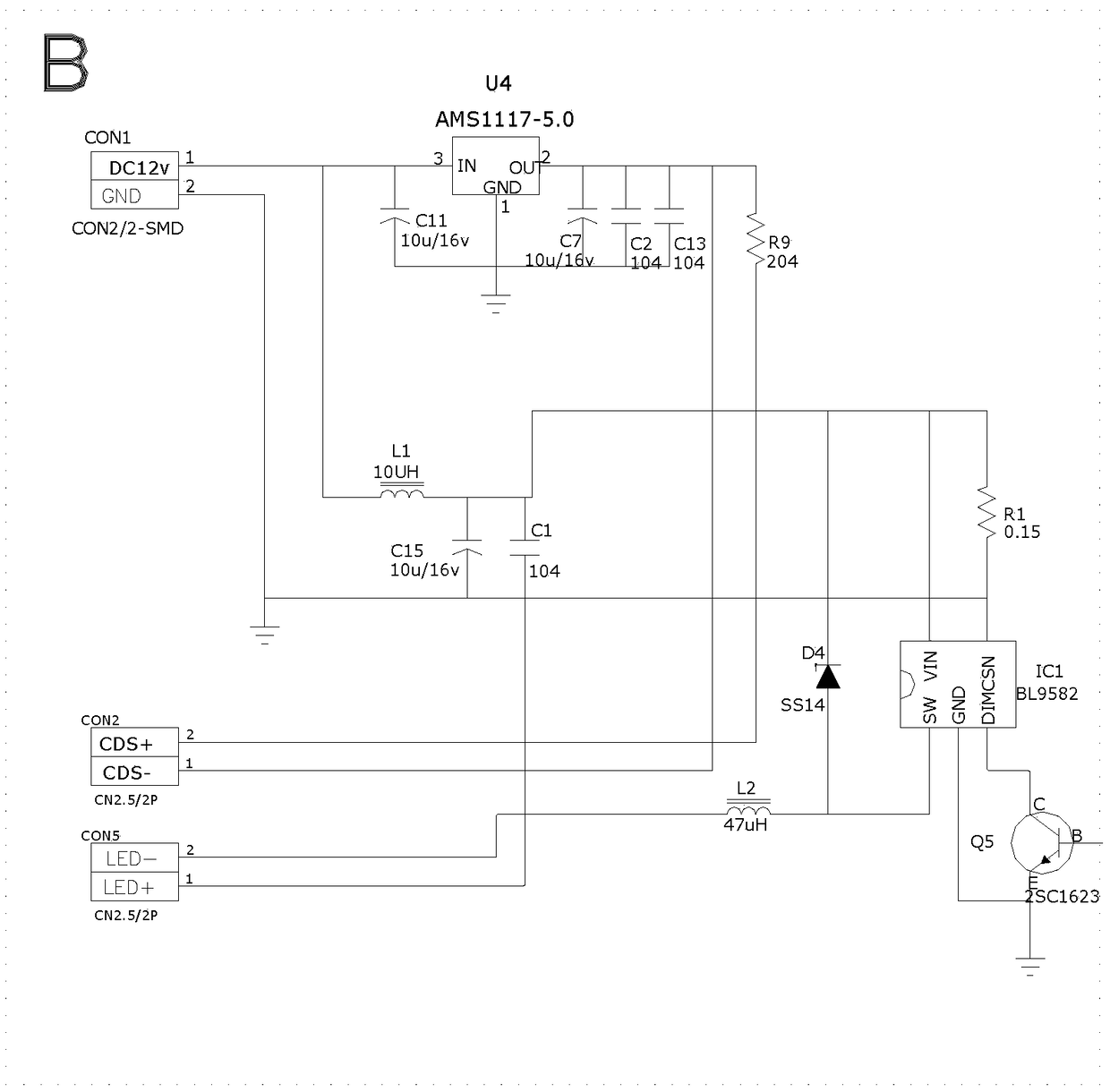
[0035] see Figure 1-4 As shown, the present invention provides a camera supplementary light control circuit, the circuit includes a power supply module, supplementary light module and photosensitive module, the circuit also includes a main control module, the power supply module is connected with the main control module, photosensitive module and photosensitive module respectively The modules are connected, the photosensitive module and the supplementary light module are connected with the main cont...


PUM


Abstract

The invention discloses a camera fill light control circuit. The camera fill light control circuit includes a power module, a fill light module and a photosensitive module. The circuit further comprises a main control module. The power module is connected with the main control module, the photosensitive module and the fill light module. The photosensitive module and the fill light module are all connected to the main control module. The invention also discloses a camera fill light control method. The method includes: reading an external brightness parameter G2 again by delaying three seconds after a fill light is turned on; adding an external illumination reference value into the brightness parameter G2 to obtain a T1; re-reading an external brightness parameter G3 at this time; comparingthe current external brightness parameter G3 with the T1, turning off the light if the G3 is greater than the T1, and keeping turn-on of the fill light if the G3 is less than T1. The main control module is added to the circuit provided by the invention, and the set control program is burned into the main control module, thereby controlling the fill light module to be turned on or off at the righttime; the strobe of the fill light can be avoided, and the power consumption of the whole circuit is reduced; and the camera can achieve the best surveillance image quality.

Description

technical field [0001] The invention belongs to the technical field of photography, and in particular relates to a camera supplementary light control circuit and a control method thereof. Background technique [0002] The 24-hour monitoring of the designated area by the camera is a common security method for people. Due to the limitation of the photosensitive technology of the camera sensor, it cannot be used at night. Therefore, the camera manufacturer will add a supplementary light (infrared light or visible light) to the camera that manufactures the monitor. It is used at night to meet the needs of night vision monitoring. [0003] For example, the patent application document with the patent application number "201620273103.X" discloses a security monitoring device, including a housing, the housing is a hemispherical shell, and a circuit board, a camera, and a rotating device are arranged in the housing. The housing is connected to the bracket, and the housing can be aut...

Claims


Application Information

Patent Timeline
Patent Type & Authority Applications(China)
IPC IPC(8): H04N5/232H04N5/235
CPCH04N23/617H04N23/65H04N23/745H04N23/71
Inventor 曾祥军谢智高
Owner 深圳市威特迪科技有限公司
Learn More