
A Modulo 2 Based on Quantum Superposition n Subtractor Design Method

A design method, quantum superposition technology, applied in CAD circuit design, special data processing applications, etc.

Active Publication Date: 2022-07-12
EAST CHINA JIAOTONG UNIVERSITY
View PDF6 Cites 0 Cited by
  • Summary
  • Abstract
  • Description
  • Claims
  • Application Information

AI Technical Summary

Problems solved by technology

[0021] The purpose of the present invention is, in order to solve the quantum subtraction operation problem of quantum superposition state, propose a kind of modulus 2 based on quantum superposition state n Subtractor design method

Method used


Image

  • A Modulo 2 Based on Quantum Superposition  <sup>n</sup> Subtractor Design Method
  • A Modulo 2 Based on Quantum Superposition  <sup>n</sup> Subtractor Design Method
  • A Modulo 2 Based on Quantum Superposition  <sup>n</sup> Subtractor Design Method

Examples


specific Embodiment approach

[0085] A mode 2 based on quantum superposition state in this embodiment n A method for designing a subtractor, the method for realizing a design method of a quantum half-subtractor and a resetter, a quantum total subtractor and a resetter using a fundamental quantum controlled gate, and a quantum half-subtractor, a quantum full-subtractor and a reset device constitute n Bit Quantum Modulus 2 n The design method of the subtractor; finally use the designed modulo 2 n Subtractor realizes modulo 2 based on quantum superposition state n Subtraction operation.

[0086] 1. The design method of the quantum half-subtractor and reset device in this embodiment

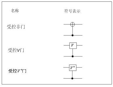
[0087] This embodiment uses four controlled gates to achieve figure 2 The quantum half-subtractor design circuit shown, its schematic diagram is as follows image 3 shown, represented by the symbol Q. Four controlled gates include one controlled NOT gate, two controlled V gates and one controlled V gate + Door.

[0088] ...


PUM


Abstract

A Modulo 2 Based on Quantum Superposition n Subtractor design method, the method uses basic quantum controlled gate to realize the design method of quantum half subtractor and reset, quantum total subtractor and reset, and constitute n by quantum half subtractor, quantum total subtractor and reset Bit Quantum Modulus 2 n The design method of the subtractor; finally use the designed modulo 2 n Subtractor realizes modulo 2 based on quantum superposition state n Subtraction operation. The invention solves the quantum mode 2 of the quantum superposition state n Subtraction problem, designed a quantum modulo 2 based on quantum superposition state n Subtractor. The invention embodies the high efficiency of quantum information processing in signal processing: only 14n‑13 basic operations can be used to achieve 2 m n-bit integers modulo 2 n Subtraction operations, while implementing the corresponding addition operations on a classical computer requires O(n2 m ) basic operation. Quantum modulus 2 of n qubits of the present invention n Quantum circuit diagram of a subtractor.

Description

technical field [0001] The invention relates to a mode 2 based on quantum superposition state n A subtractor design method belongs to the technical field of quantum circuit design. Background technique [0002] Modulo 2 n Subtraction is expressed as [0003] MS(b-a)=sign(b-a)×[(b-a)mod 2 n ] (1) [0004] where a and b are n-bit positive integers. When b<a, sign(b-a)=-1, and when b≥a, sign(b-a)=1. (b-a)mod 2 n is (b-a) to 2 n Perform the modulo operation, the operation rules are as follows [0005] [0006] In quantum computing, an information unit is represented by a quantum bit, which has two fundamental quantum states |0> and |1>, and the fundamental quantum states are referred to as ground states for short. A qubit can be a linear combination of two ground states, often called a superposition state, which can be expressed as |ψ>=a|0>+b|1>, where a and b are two complex numbers. [0007] The tensor product is a method of combining small vecto...

Claims


Application Information

Patent Timeline
Patent Type & Authority Patents(China)
IPC IPC(8): G06F30/36
CPCG06F30/36
Inventor 范萍黎海生丁振凡殷爱菡
Owner EAST CHINA JIAOTONG UNIVERSITY
Learn More