Vertical profile traction robot

A robot and vertical technology, applied in the field of metal processing, can solve the problems of increasing the footprint of the profile pulling manipulator, and it is difficult to ensure the straightness and straightness of the profile pulling manipulator, so as to achieve stable grasping and reduce the floor space. , the effect of improving quality

Pending Publication Date: 2018-12-04
广东省智行机器人科技有限公司
View PDF7 Cites 0 Cited by
  • Summary
  • Abstract
  • Description
  • Claims
  • Application Information

AI Technical Summary

Problems solved by technology

Although the horizontal walking mechanism can realize the walking movement of the mechanical arm, it is difficult to ensure the straightness and straightness of the profile-drawn mechanical arm because it is easily affected by the ground conditions. The tracks on the ground cooperate with each other, which greatly increases the space occupied by the movement of the profile traction manipulator

Method used


Image

  • Vertical profile traction robot
  • Vertical profile traction robot
  • Vertical profile traction robot

Examples


Embodiment 1

[0053] This embodiment takes the vertical formation of a double-track traction robot as an example to describe the following.

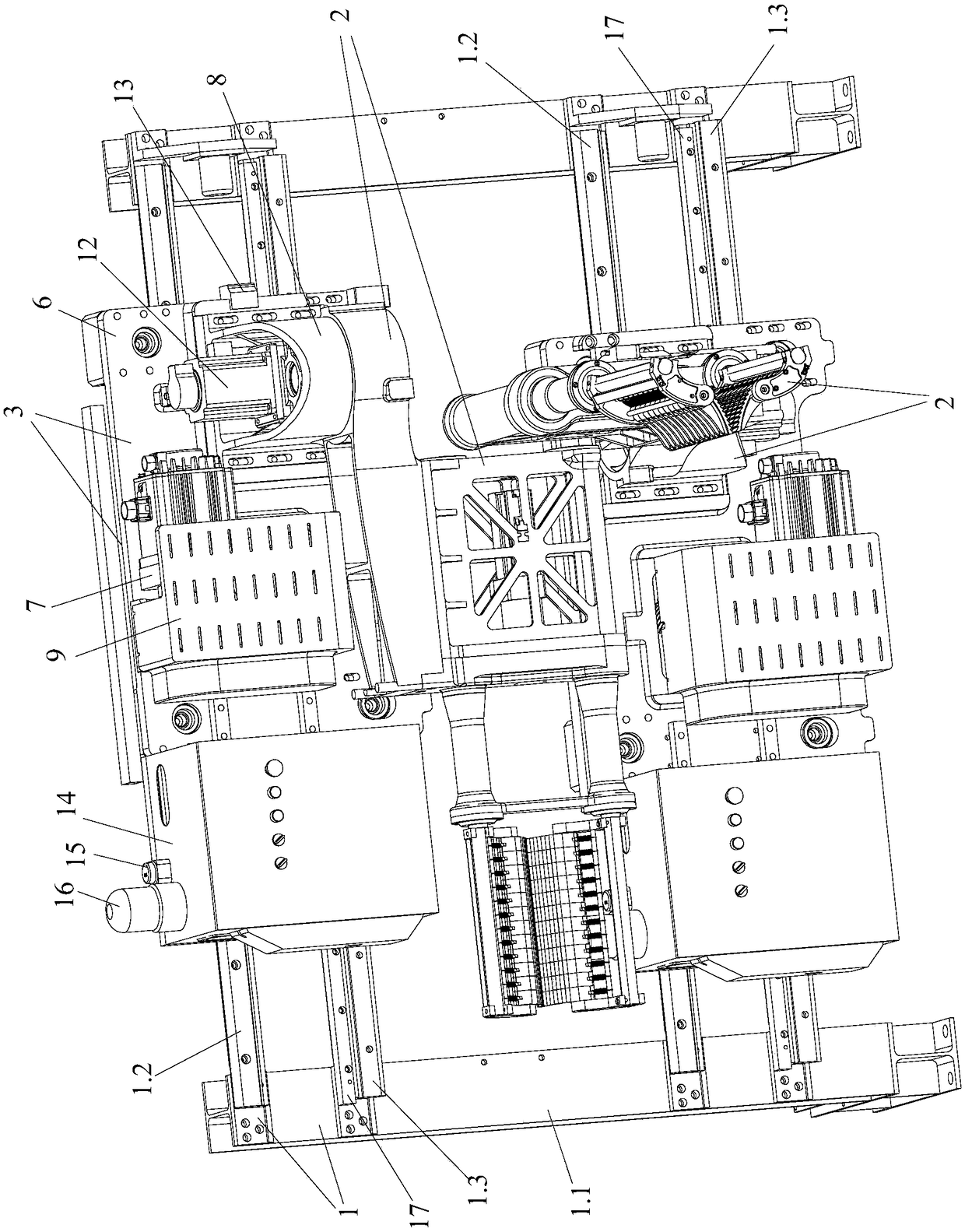
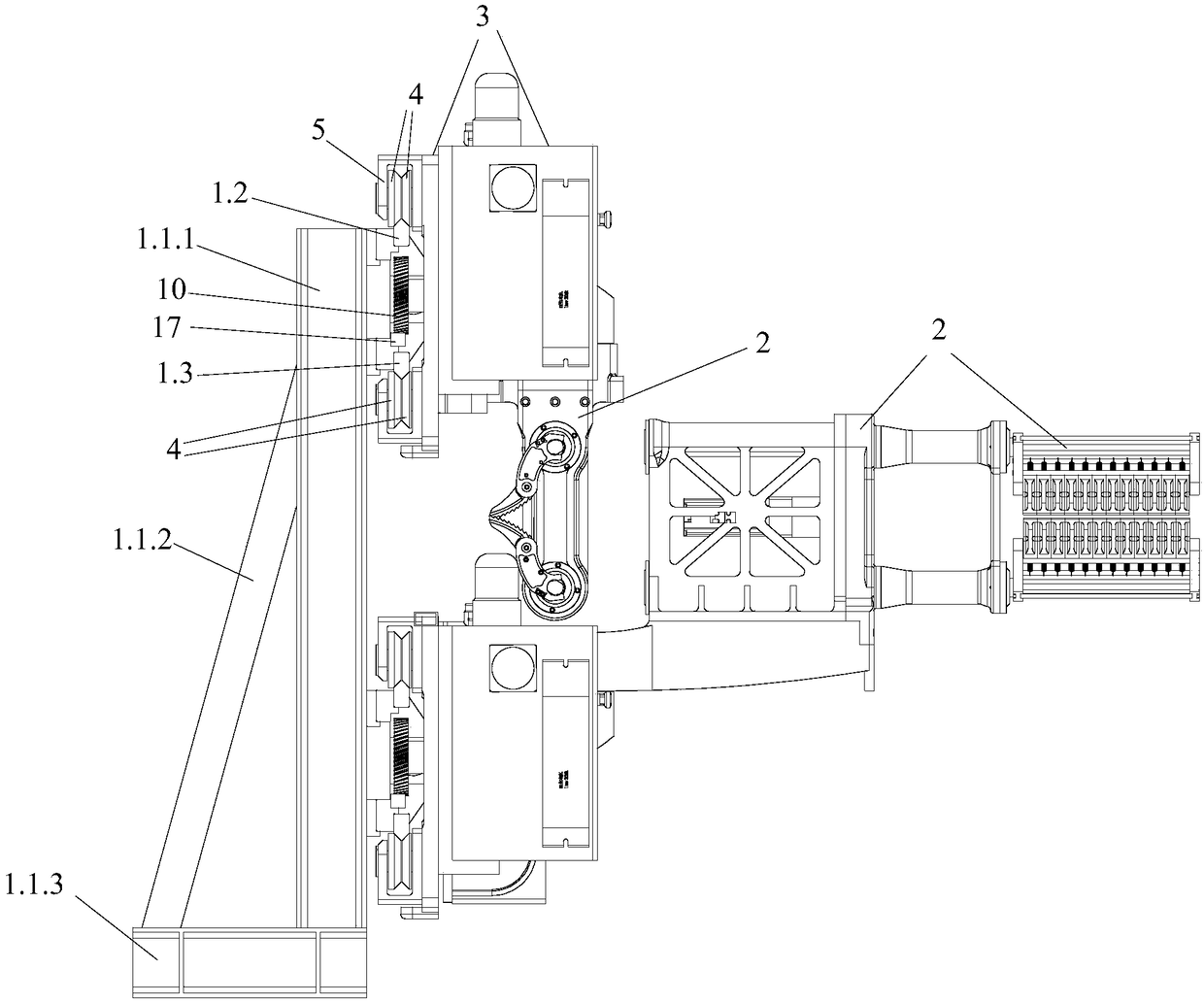
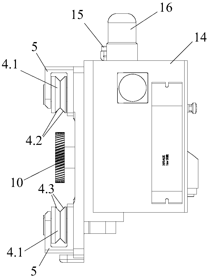
[0054] Such as Figures 1 to 9 As shown, the vertical profile traction robot of the present invention includes a vertical walking guide rail 1, two traction units and a control mechanism 14, wherein each traction unit includes a mechanical arm 2 for clamping traction profiles 18, for The walking guide rail 1 is slidably connected to realize the carriage 3 of the walking movement of the mechanical arm 2, wherein the mechanical arm 2 is clamped on the side of the vertical walking guide rail 1 through the carriage 3, and is slidably connected with the side of the vertical walking guide rail 1, Realize that the mechanical arm 2 is suspended on the side of the vertical walking guide rail 1 for walking movement, and the control mechanism 14 is respectively connected with the carriage 3 and the mechanical arm 2 with signals.

[0055] The two traction units ...

Embodiment 2

[0069] The only difference between this embodiment and the implementation is that this embodiment is a multi-track vertical profile traction robot, which includes a control mechanism, a vertical walking guide rail and is composed of three or more traction units, three traction units Parallel up and down on the vertical walking guide rail, the mechanical arms of two adjacent traction units are suspended on the vertical walking guide rail for coordinated and alternate walking movement, so as to realize the traction of profiles in a coordinated and alternate manner.

[0070] The structure of each traction unit, control mechanism and vertical walking guide rail in this embodiment is consistent with Embodiment 1.


PUM


Abstract

The invention provides a vertical profile traction robot. The vertical profile traction robot comprises a vertical walking guide rail, M traction units and a control mechanism, wherein every tractionunit includes a mechanical arm for clamping a traction profile and a sliding rack in sliding connection with the vertical walking guide rail to make the mechanical arm walk and move; the mechanical arm is clamped on the side surface of the vertical walking guide rail by the sliding rack, and is in sliding connection with the side surface of the vertical walking guide rail in order to realize the walking and movement of the mechanical arm hanging on the side surface of the vertical walking guide rail; the control mechanism is in signal connection with the sliding rack and the mechanical arms respectively ; and the M traction units are arranged on the vertical walking guide rail in parallel up and down, and the mechanical arms of the two adjacent traction units hang and synergistically alternately walk and move on the vertical walking guide rail in order to tract the profile in a synergistic alternate manner. The vertical profile traction robot can automatically tract the profile in a multi-track manner according to production demands in order to improve the profile traction efficiency.

Description

technical field [0001] The invention relates to the technical field of metal processing, and more specifically relates to a vertical profile pulling robot. Background technique [0002] In mechanical manufacturing, when processing long pipes and other workpieces, traction devices are often required for auxiliary traction processing, so as to cut and process the workpieces. Existing traction devices usually include a linear reciprocating mechanism and a fixture capable of clamping the workpiece. After the fixture clamps the workpiece, the drive device drives the fixture to pull, thereby realizing continuous production of profiles. The use of traction device can improve the production quality and qualification rate of profiles, and the stability of traction device operation is closely related to the quality of produced profiles. [0003] In the traction process using the traction device, the prior art uses a moving clamping gripper to grasp and traction the profiles. However...

Claims


Application Information

Patent Timeline
Patent Type & Authority Applications(China)
IPC IPC(8): B21C35/02
CPCB21C35/02
Inventor 刘杰陈燕智卢佳迪
Owner 广东省智行机器人科技有限公司
Why Eureka
Try Eureka