
Flow automatic control ball valve and flow automatic control method

A technology of automatic flow control and ball valve, applied in valve device, safety valve, balance valve, etc., can solve the problems of air-conditioning system out of control, temperature fluctuating hot and cold, energy waste, etc., to achieve the effect of saving energy

Active Publication Date: 2019-08-06
HANGZHOU CHUNJIANG VALVE
View PDF5 Cites 0 Cited by
  • Summary
  • Abstract
  • Description
  • Claims
  • Application Information

AI Technical Summary

Problems solved by technology

[0004] The purpose of the present invention is to overcome the existence of the above-mentioned ball valve. When the opening of the ball, that is, the opening area of ​​the hole (throttle hole) is determined, if the pressure fluctuation at the inlet or outlet causes the pressure difference between the front and the back of the hole to change, the flow rate through the hole will be reduced. It is no longer the ideal flow required by the original design, but fluctuates with the change of pressure difference, especially when the pressure difference between the front and back of the hole is small, it will cause the air conditioning system to lose control, and the temperature of the environment will be hot and cold, making the user The user feels uncomfortable and causes energy waste. When the pressure at the inlet or outlet of the ball valve fluctuates, the pressure difference between the front and the back of the hole remains unchanged, which will not cause the air conditioning system to lose control, make the user feel comfortable, and save energy. Flow self-control ball valve and flow self-control method

Method used


Image

  • Flow automatic control ball valve and flow automatic control method
  • Flow automatic control ball valve and flow automatic control method
  • Flow automatic control ball valve and flow automatic control method

Examples


Embodiment Construction

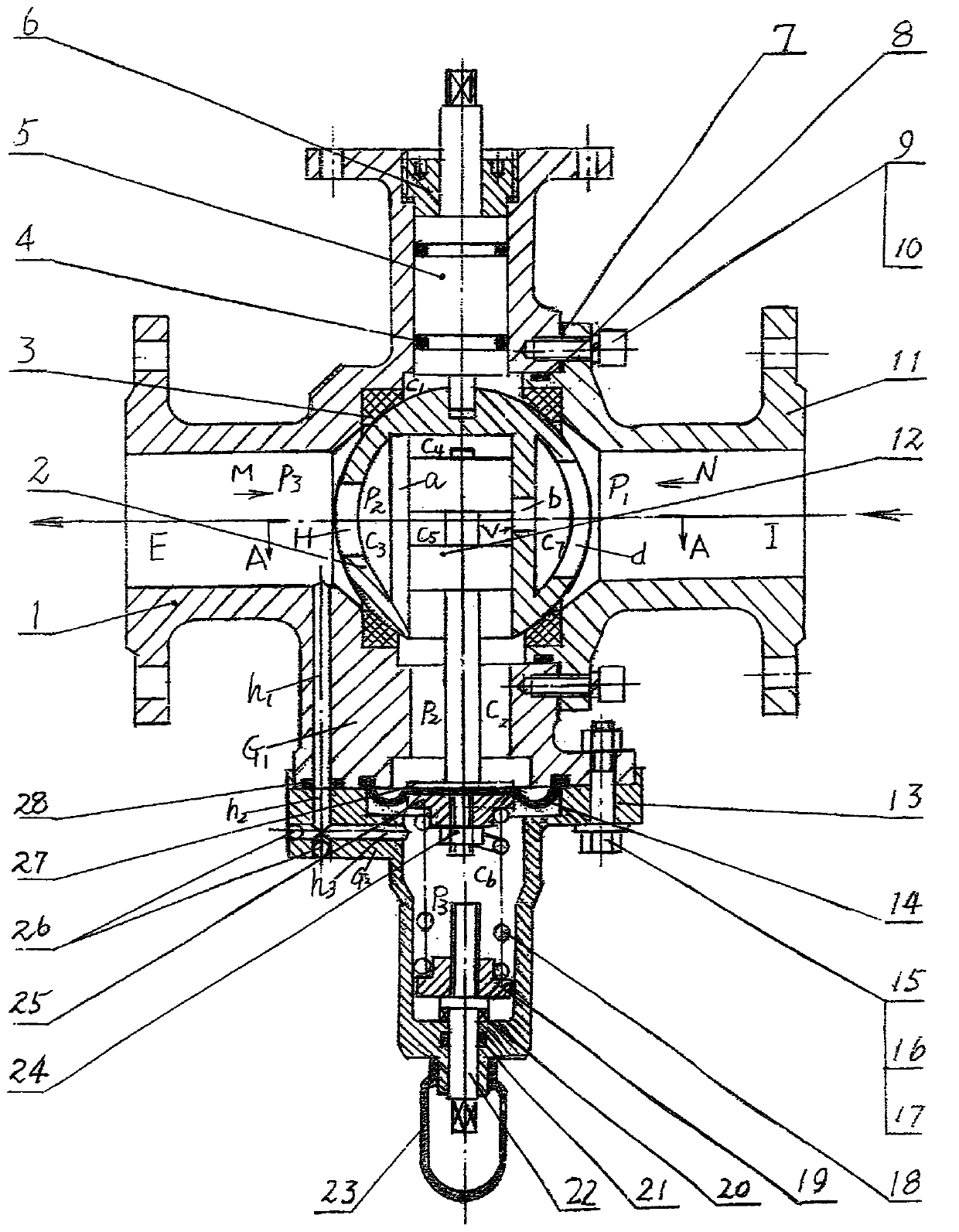
[0020] The present invention will be further described below in conjunction with the accompanying drawings.

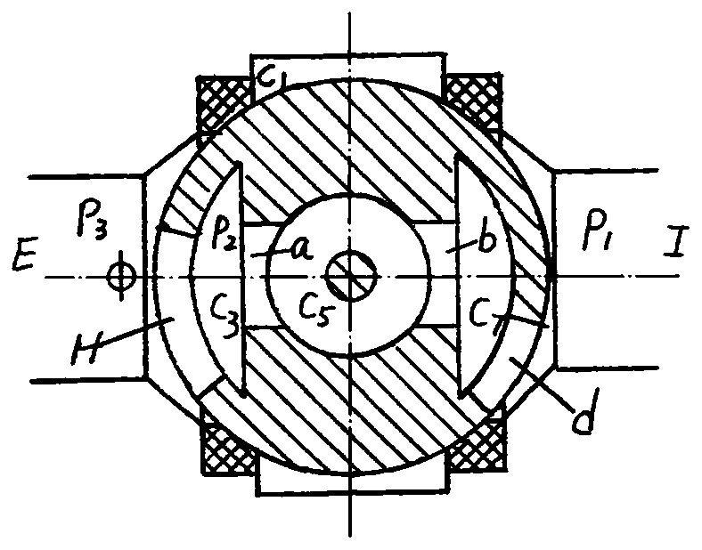
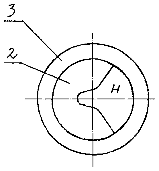
[0021] as attached figure 1 to attach Figure 6 Shown, the present invention is made up of two parts of ball valve and differential decompression valve.

[0022]Ball valve is made up of parts such as valve body 1, spheroid 2, valve seat 3, O-shaped sealing ring 4, upper valve stem 5, screw sleeve 6, gasket 7, O-shaped sealing ring 2 8, and right side cover 11. Valve body 1 is a four-way valve body. The through hole of the left end cylinder is the water outlet hole E, which is located on the same horizontal axis as the right end through hole. The through holes of the upper and lower cylinders are on the same vertical axis. The two axes intersect vertically. There is a circular pit on the inner wall of the inner cavity at the right end, and the flange at the left end is connected to the corresponding flange of the downstream pipeline. For small diameter ball valves, th...


PUM


Abstract

The invention relates to a flow self-control spherical valve and a flow self-control method. The flow self-control spherical valve is provided with a spherical valve and a fixed differential pressure-reducing valve. The spherical valve comprises a four-way valve body and a right side cover, wherein the four-way valve body is provided with with three sides of upper, lower and left barrels; a valveseat, a sphere and an upper valve rod are arranged in the valve body; the right side cover is mounted at the right end of the valve body and is provided with a barrel; a blind hole is formed at the lower end of the sphere; a throttling hole is formed on the sphere wall of the left side of the sphere; an oval water inlet is formed at the inclined left position on the sphere wall of the right side of the sphere; by rotating the upper valve rod, the opening of the throttling hole can be regulated; the fixed differential pressure-reducing valve is connected in series in front of the throttling hole and comprises a sliding valve in sliding fit in the blind hole and a diaphragm mounted between the lower end face of the valve body and a bottom cover; the sliding valve and the diaphragm are connected into one whole body; a pressure difference regulation device comprising a pressure regulation screw, a pressure regulation screw sleeve, a spring and the like is arranged in a cavity between the bottom cover and the diaphragm; when a medium passes through the throttling hole, due to the pressure compensation effect of the fixed differential pressure-reducing valve, even though water pressuresat water inlet and outlets are fluctuated, the pressure difference between both ends of the throttling hole can be kept unchanged, thereby ensuring that passing flow is constant.

Description

technical field [0001] The invention relates to the field of flow regulating valves, in particular to a flow self-control ball valve and a flow self-control method. Background technique [0002] Due to its compact structure, good sealing performance and easy operation, ball valves have been widely used in the function of regulating flow in recent years. Because a through hole with a certain flow characteristic shape is processed on the spherical wall of the hollow sphere, the functional relationship between the relative opening of the sphere and the passing flow can be easily realized, so that the ball valve has certain flow characteristics, such as linear flow characteristics, etc. Percentage flow characteristics, quick opening flow characteristics and parabolic flow characteristics, etc. For example, in the air conditioning system, the control system generally adopts linear control, and the specific method is as follows: the characteristic of the coil is that a small flow...

Claims


Application Information

Patent Timeline
Patent Type & Authority Patents(China)
IPC IPC(8): F16K17/30
CPCF16K17/30
Inventor 柴为民陈永新
Owner HANGZHOU CHUNJIANG VALVE
Learn More