Pump body assembly, fluid machine and heat exchange equipment
A component and pump body technology, which is applied in the direction of mechanical equipment, pump components, liquid fuel engines, etc., can solve the problems of easy eccentric rotation of the piston sleeve and affect the working efficiency of the pump body components, etc., and achieve the goal of improving operation reliability and performance Effect
- Summary
- Abstract
- Description
- Claims
- Application Information
AI Technical Summary
Problems solved by technology
Method used
Image


Examples
Embodiment 2
[0078] The difference between the pump body assembly in the second embodiment and the first embodiment lies in that the structures of the structural parts are different.
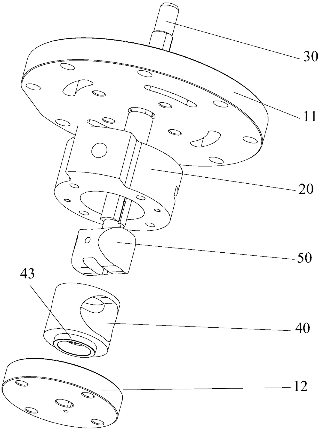
[0079] Such as Figure 5 to Figure 7 As shown, at least two structural parts include a lower flange 12 and a lower limiting plate 13, the lower limiting plate 13 and the lower flange 12 are located below the cylinder 20, and the lower limiting plate 13 is located between the cylinder 20 and the lower flange 12 , the limit protrusion 43 and the lower limit plate 13 limit stoppers to prevent the radial displacement of the piston sleeve 40 relative to the lower limit plate 13 .
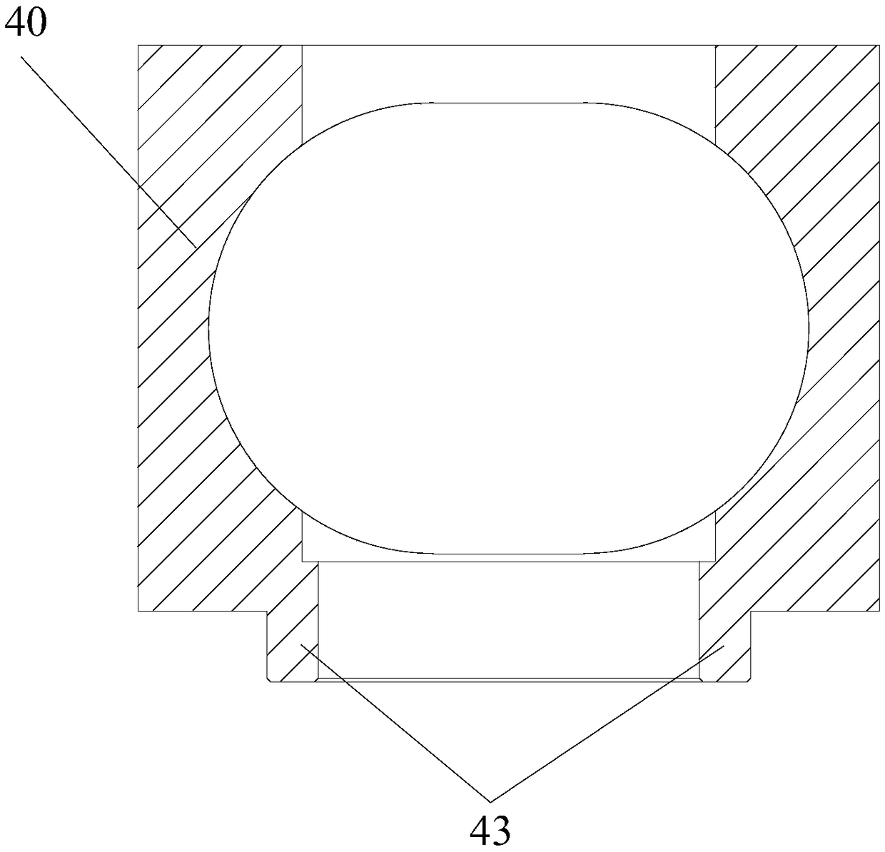
[0080] Such as Figure 5 to Figure 7 As shown, the limiting protrusion 43 extends into the central hole of the lower limiting plate 13 , and is limitedly engaged with the inner surface of the central hole of the lower limiting plate 13 . In this way, during the operation of the pump body assembly, the hole wall of the central hole of...
Embodiment 3
[0084] The difference between the pump body assembly in the third embodiment and the second embodiment is that the structure of the lower limiting plate 13 is different.
[0085] Such as Figure 8 to Figure 12 As shown, the surface of the lower limit plate 13 facing the piston sleeve 40 has a fourth limit groove 131, and the limit protrusion 43 extends into the fourth limit groove 131 and stops with the fourth limit groove 131. . In this way, during the operation of the pump body assembly, the outer surface of the limit protrusion 43 is limitedly matched with the groove wall of the fourth limit groove 131 to realize the limit of the radial direction of the piston sleeve 40 by the lower limit plate 13 , so that the operation of the piston sleeve 40 is more stable, and the operation reliability of the pump body assembly is improved.
[0086] Optionally, the fourth limiting groove 131 is an annular groove, and the annular groove is arranged coaxially with the central hole of th...
Embodiment 4
[0088] The difference between the pump body assembly in the fourth embodiment and the second embodiment is that the structures of the upper flange 11 and the piston sleeve 40 are different.
[0089] Such as Figure 13 to Figure 16 As shown, the lower end surface of the upper flange 11 has a limiting portion 112 extending toward the piston sleeve 40 , and the upper end of the piston sleeve 40 has a stepped surface 44 . Wherein, the step surface 44 is located at the end of the piston sleeve 40 facing the upper flange 11, and the limit portion 112 extends into the step surface 44 of the piston sleeve 40 to limit the stop of the step surface 44, so that the upper flange 11 is aligned with the piston sleeve. 40 limit support in the radial direction.
[0090] Optionally, the limiting part 112 is an annular structure, and the annular structure is eccentrically arranged with respect to the upper flange 11, and the eccentricity is e. The structure of the above structure is simple and...
PUM
 Abstract
Description
Claims
Application Information
 - Generate Ideas
- Intellectual Property
- Life Sciences
- Materials
- Tech Scout
- Unparalleled Data Quality
- Higher Quality Content
- 60% Fewer Hallucinations
Browse by: Latest US Patents, China's latest patents, Technical Efficacy Thesaurus, Application Domain, Technology Topic, Popular Technical Reports.
© 2025 PatSnap. All rights reserved.Legal|Privacy policy|Modern Slavery Act Transparency Statement|Sitemap|About US| Contact US: help@patsnap.com