
Tile side bottom gap automatic filling device

An automatic filling and tile technology, which is applied in the direction of architecture and building construction, etc., can solve problems such as waste of resources, cracked tiles, large gaps at the side and bottom of tiles, etc., and achieve the effect of speeding up filling and saving material costs

Inactive Publication Date: 2018-11-30
沈喜刚
View PDF7 Cites 0 Cited by
  • Summary
  • Abstract
  • Description
  • Claims
  • Application Information

AI Technical Summary

Problems solved by technology

[0002] With the advancement and development of science and technology, people's living standards have improved, and the living standards have also increased. When laying tiles on the ground, due to improper laying levels, the gap at the bottom of the tile side is too large. After a long time, the tiles will be broken and damaged. At the same time, when replacing tiles Sometimes the tiles can only be replaced if they are destroyed, wasting resources

Method used


Image

  • Tile side bottom gap automatic filling device
  • Tile side bottom gap automatic filling device
  • Tile side bottom gap automatic filling device

Examples


Embodiment 1

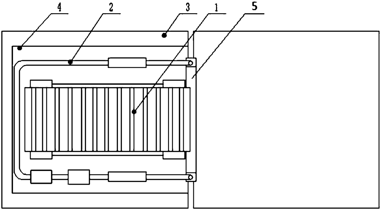
[0023] Embodiment 1: An automatic filling device for the gap at the bottom of the tile side, including: a transmission device 1, a sealing device 5, an iron powder conveying device 2 and a U-shaped base 4,

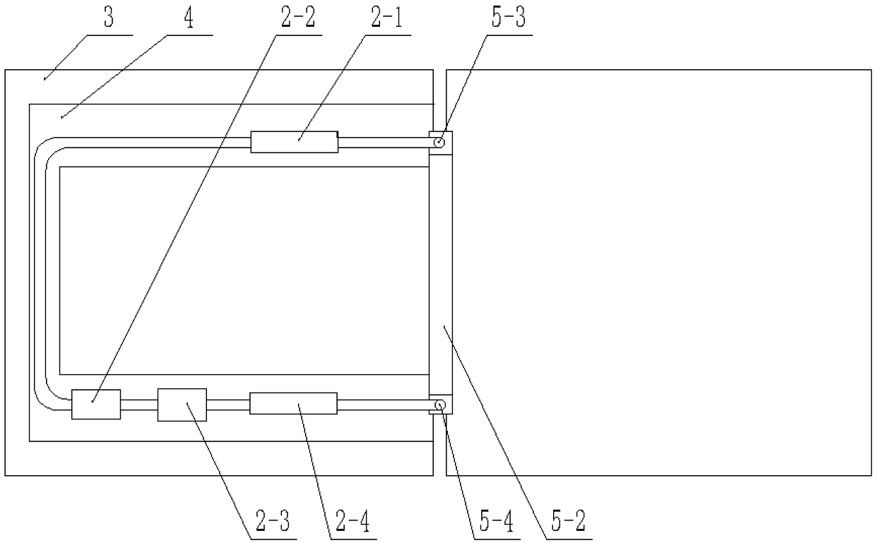
[0024] The upper surface of the ceramic tile 3 is provided with a U-shaped base 4, and the U-shaped base 4 is provided with a transmission device 1. The transmission device 1 is located directly above the gap at the bottom of the ceramic tile 3, and a sealing device 5 is provided in the gap of the ceramic tile 3. On the U-shaped base 4, An iron powder conveying device 2 is provided, and the iron powder conveying device 2 is connected with the sealing device 5 through a pipeline.

Embodiment 2

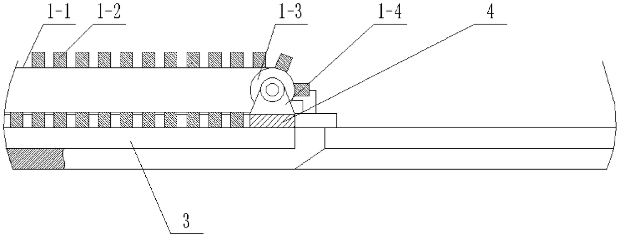
[0025] Embodiment 2: The transmission device 1 includes: a transmission belt 1-1, an electromagnet 1-2, a transmission roller 1-3 and a bearing seat 1-4, and the four corners of the U-shaped base 4 are provided with bearing seats 1-4 , the two ends of the transmission roller 1-3 are connected with the bearing seat 1-4, one end of the transmission roller 1-3 is connected with the output end of the drive motor, the transmission roller 1-3 is covered with a transmission belt 1-1, and the transmission belt 1-1 is provided with multiple The electromagnet 1-2, the driving motor and the electromagnet 1-2 are all connected to the controller arranged on the U-shaped base 4 through lines, so that the electromagnet 1-2 under the transmission belt 1-1 is energized sequentially from left to right , can absorb the iron powder delivered to achieve the purpose of filling, and at the same time, the rotation of the transmission belt 1-1 drives the iron powder to move to the interior of the botto...

Embodiment 3

[0026] Embodiment 3: The sealing device 5 includes: a sealing block 5-1, a sealing cover plate 5-2, an iron powder outlet 5-3 and an iron powder inlet 5-4, and two sealing blocks are arranged in the gap between the tiles 3 5-1, the sealing block 5-1 is located at the two ends of the gap at the bottom of the ceramic tile 3, the sealing cover 5-2 is arranged above the sealing block 5-1, and the two ends of the upper end surface of the sealing cover 5-2 are respectively provided with iron The powder outlet 5-3 and the iron powder inlet 5-4, the iron powder outlet 5-3 and the iron powder inlet 5-4 are all connected to each other with the iron powder conveying device 2 through pipelines, so that it is arranged to ensure that the iron powder and air are not mixed. Leakage occurs, saving iron powder.


PUM


Abstract

The invention relates to a tile side bottom gap automatic filling device. The automatic filling device comprises a transmission device, a sealing device, an iron powder conveying device and a U-shapedbase. The upper surface of a tile is provided with the U-shaped base, and the U-shaped base is provided with the transmission device located right above the tile side bottom gap. The sealing device is arranged in the tile gap, and the U-shaped base is provided with the iron powder conveying device connected to the sealing device through the pipeline. The automatic filling device solves the problem that the laid tile side bottom cannot be filled, and greatly saves the material cost. The automatic filling device adopts the method of mixing air and iron powder for conveying, and can increase thefilling speed and the filling saturation. The automatic filling device adopts belt transmission to drive an electromagnet to rotate, iron powder entering the tile side bottom can be moved inwards toachieve the effect of compacting and ensure that the tile side bottom is not damaged due to external force.

Description

technical field [0001] The invention relates to the technical field of tile filling, in particular to an automatic filling device for the gap at the bottom of the tile side. Background technique [0002] With the advancement and development of science and technology, people's living standards have improved, and the living standards have also increased. When laying tiles on the ground, due to improper laying levels, the gap at the bottom of the tile side is too large. After a long time, the tiles will be broken and damaged. At the same time, when replacing tiles Sometimes the tiles can only be replaced if they are destroyed, which wastes resources. Contents of the invention [0003] The object of the present invention is to provide an automatic filling device for the gap at the bottom of the tile side, so as to solve the problems raised in the above-mentioned background technology. [0004] An automatic filling device for the gap at the bottom of the tile side, including: ...

Claims


Application Information

Patent Timeline
Patent Type & Authority Applications(China)
IPC IPC(8): E04F21/22
CPCE04F21/22
Inventor 沈喜刚
Owner 沈喜刚
Learn More