
Fabric printing and dyeing pre-wetting device and method

A fabric, printing and dyeing pool technology, applied in the field of fabric or fabric printing and dyeing, can solve the problems of decreased dye concentration, affecting printing and dyeing quality, poor pre-wetting effect, etc., to achieve the effect of eliminating wrinkles and improving printing and dyeing quality

Inactive Publication Date: 2018-11-30
余文冰
View PDF9 Cites 3 Cited by
  • Summary
  • Abstract
  • Description
  • Claims
  • Application Information

AI Technical Summary

Problems solved by technology

However, at present, the pre-wetting of printing and dyeing is often done manually, which is not efficient and the pre-wetting effect is not good.
[0003] Such as CN 207295194 U discloses a kind of high-efficiency cloth printing and dyeing pre-wetting device, which can carry out pre-wetting treatment to the cloth for printing and dyeing, which not only plays a role in cleaning the cloth, but also facilitates the adhesion of dyestuffs when printing and dyeing, and improves the At the same time, the water used for pre-wetting can be reused, which reduces the waste of water; but there is a fatal problem: when the cloth enters the dye tank from the clear water tank, due to the moisture absorbed on the cloth, the water Dissolving in the dye tank will cause the concentration of the dye to drop, affecting the final printing and dyeing quality

Method used


Image

  • Fabric printing and dyeing pre-wetting device and method
  • Fabric printing and dyeing pre-wetting device and method
  • Fabric printing and dyeing pre-wetting device and method

Examples


Embodiment 1

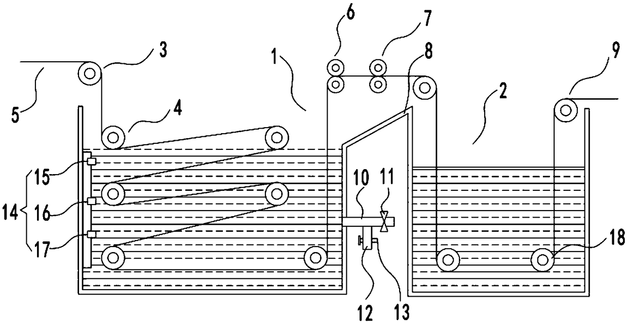
[0024] See figure 1 In the embodiment of the present invention, a fabric printing and dyeing pre-wetting device includes a prepreg tank 1, a printing and dyeing tank 2, and a feeding guide roller 3 and a discharging guide roller 9 for guiding the movement of the cloth 5. The prepreg tank 1 and the dyeing tank 2 are respectively installed with a soaking guide roller group 4 and a printing and dyeing guide roller group 18, the fabric 5 passes through the feed guide roller 3 and is wound around the soaking guide roller group 4 and then enters the dyeing tank 2 and bypasses the dyeing tank The printing and dyeing guide roller set 18 in 2 is then output by the discharging guide roller 9. Of course, in this embodiment, there are also a discharging roller for discharging and a receiving roller for receiving, in order to make the technical solution more Concise, this technical solution does not illustrate it. Generally speaking, its working principle is as follows: the cloth 5 output fr...

Embodiment 2

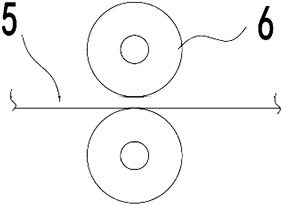
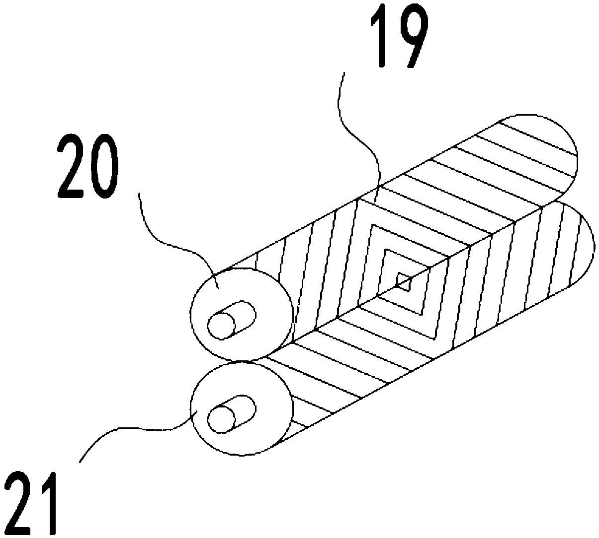
[0027] See figure 2 with 3 In this embodiment, the squeeze roller 6 and the smoothing roller 7 in the embodiment 1 are explained, and the details are as follows:

[0028] The squeeze roller 6 is composed of a pair of relatively rotating rollers. The cloth 5 passes between the rollers. The gap between the rollers is smaller than the thickness of the cloth 5. When working, the water in the cloth 5 can be squeezed out. , And drip on the diversion slope 8, and finally return to the prepreg tank 1.

[0029] The smoothing roller 7 includes a relatively rotating roller body 20 and a roller body 21. The cloth 5 passes between the roller body 20 and the roller body 21. The surfaces of the roller body 20 and the roller body 21 are both provided. There are multiple diagonal lines 19, which spread from the middle of roller body one 20 and roller body two 21 to both ends. The wrinkles on the surface of the cloth 5 can be stretched to both sides by the outward spreading diagonal lines 19 to ens...

Embodiment 3

[0031] See figure 1 with 4 In order to enrich the functions of the prepreg tank 1 and make the prepreg operation more convenient, a liquid level sensor 14 for detecting the liquid level is installed in the prepreg tank 1. The liquid level sensor 14 is composed of high-level sensors 15, which are distributed up and down. The middle position sensor 16 and the low position sensor 17 are composed. The high position sensor 15, the middle position sensor 16 and the low position sensor 17 are all connected to the central control host. One side of the prepreg tank 1 is also connected with a water inlet pipe 10, which is connected to an external storage The water mechanism is connected. The inlet pipe 10 is equipped with an inlet pipe solenoid valve 11 controlled by the central control host. When the water level in the prepreg pool 1 is lower than the low level sensor 17, the low level sensor 17 sends a signal to the central control host, and the central control host receives After the s...


PUM


Abstract

The invention discloses a fabric printing and dyeing pre-wetting device. The fabric printing and dyeing pre-wetting device comprises a pre-impregnation tank, a printing and dyeing tank, and a feedingguide roller and a discharging guide roller which are used for guiding the movement of a fabric, wherein a water immersion guide roller set and a printing and dyeing guide roller set are mounted in the pre-impregnation tank and the printing and dyeing tank respectively; after the fabric passes through the feeding guide roller, the fabric is wound into the water immersion guide roller set and thenenters the printing and dyeing tank; after the fabric is wound around the printing and dyeing guide roller set in the printing and dyeing tank, the fabric is output from the discharging guide roller;an extruding roller for extruding and dehydrating the fabric and a leveling roller for taking out folds are mounted at a position between the pre-impregnation tank and the printing and dyeing tank. The fabric printing and dyeing pre-wetting device disclosed by the invention has the beneficial effects that the extruding roller and the leveling roller are arranged between the pre-impregnation tank and the printing and dyeing tank, and can be used for guiding water extruded by the extruding roller to flow back into the pre-impregnation tank and preventing a condition that a lot of the water fromentering the printing and dyeing tank so that the concentration of a dyestuff in the printing and dyeing tank is obviously reduced is prevented; relatively great influences on the quality of final finished products are not caused; the fabric also can be leveled to eliminate the folds, so that the printing and dyeing quality is improved.

Description

Technical field [0001] The invention relates to the technical field of fabric or cloth printing and dyeing, in particular to a cloth printing and dyeing pre-wetting device and a pre-wetting method. Background technique [0002] Because printed fabrics often have certain impurities on the surface before they are dyed, and due to the differences in the material properties of various fabrics, the dyes sometimes cannot fully adhere to the fabrics. Therefore, it is necessary to perform pre-treatment on the fabric before printing and dyeing, and printing and dyeing pre-wetting is one of the pre-treatment processes on the fabric. However, the current printing and dyeing pre-wetting is often done manually, which is not efficient and the pre-wetting effect is not good. [0003] For example, CN 207295194 U discloses a high-efficiency fabric printing and dyeing pre-wetting device, which can pre-wet the fabrics to be printed and dyed, which not only plays a role in cleaning the fabrics, but a...

Claims


Application Information

Patent Timeline
Patent Type & Authority Applications(China)
IPC IPC(8): D06B3/10D06B23/20D06B15/02D06B23/00
CPCD06B3/10D06B15/02D06B23/00D06B23/20
Inventor 余文冰
Owner 余文冰
Learn More