
Mold frame adjusting seat for boat building

A technology for adjusting seats and tire frames, which is applied in the direction of berths, dry docks, and ship parts, etc., can solve the problems of increasing tire frame manufacturing costs, tire frame material loss, applicability and practical limitations, etc., to improve adjustment accuracy and reduce Friction resistance, good effect of use

Inactive Publication Date: 2018-11-30
芜湖籁余新能源科技有限公司
View PDF8 Cites 2 Cited by
  • Summary
  • Abstract
  • Description
  • Claims
  • Application Information

AI Technical Summary

Problems solved by technology

The commonly used tire frame structure is generally formed by assembling and welding various steel profiles and templates, which cannot meet the manufacturing requirements, nor can it be disassembled and adjusted again. It is often remanufactured after dismantling
This will cause a lot of loss of tire frame materials, reduce the reuse rate of tire frame materials, increase the cost of tire frame manufacturing, prolong the manufacturing cycle of the tire frame, and cannot meet the market requirements of the increasingly shortened steel structure manufacturing cycle
The frame flexible tire board type universal tire frame in the prior art is mainly composed of a cabinet frame, a flexible formwork, a channel steel beam and an adjustment rod, etc. Although it can realize the segmented assembly of the ship to a certain extent, its use stability and adjustment accuracy Low, so the applicability and practicality are limited to a certain extent

Method used


Image

  • Mold frame adjusting seat for boat building
  • Mold frame adjusting seat for boat building

Examples


Embodiment Construction

[0017] The following will clearly and completely describe the technical solutions in the embodiments of the present invention with reference to the accompanying drawings in the embodiments of the present invention. Obviously, the described embodiments are only some, not all, embodiments of the present invention. Based on the embodiments of the present invention, all other embodiments obtained by persons of ordinary skill in the art without making creative efforts belong to the protection scope of the present invention.

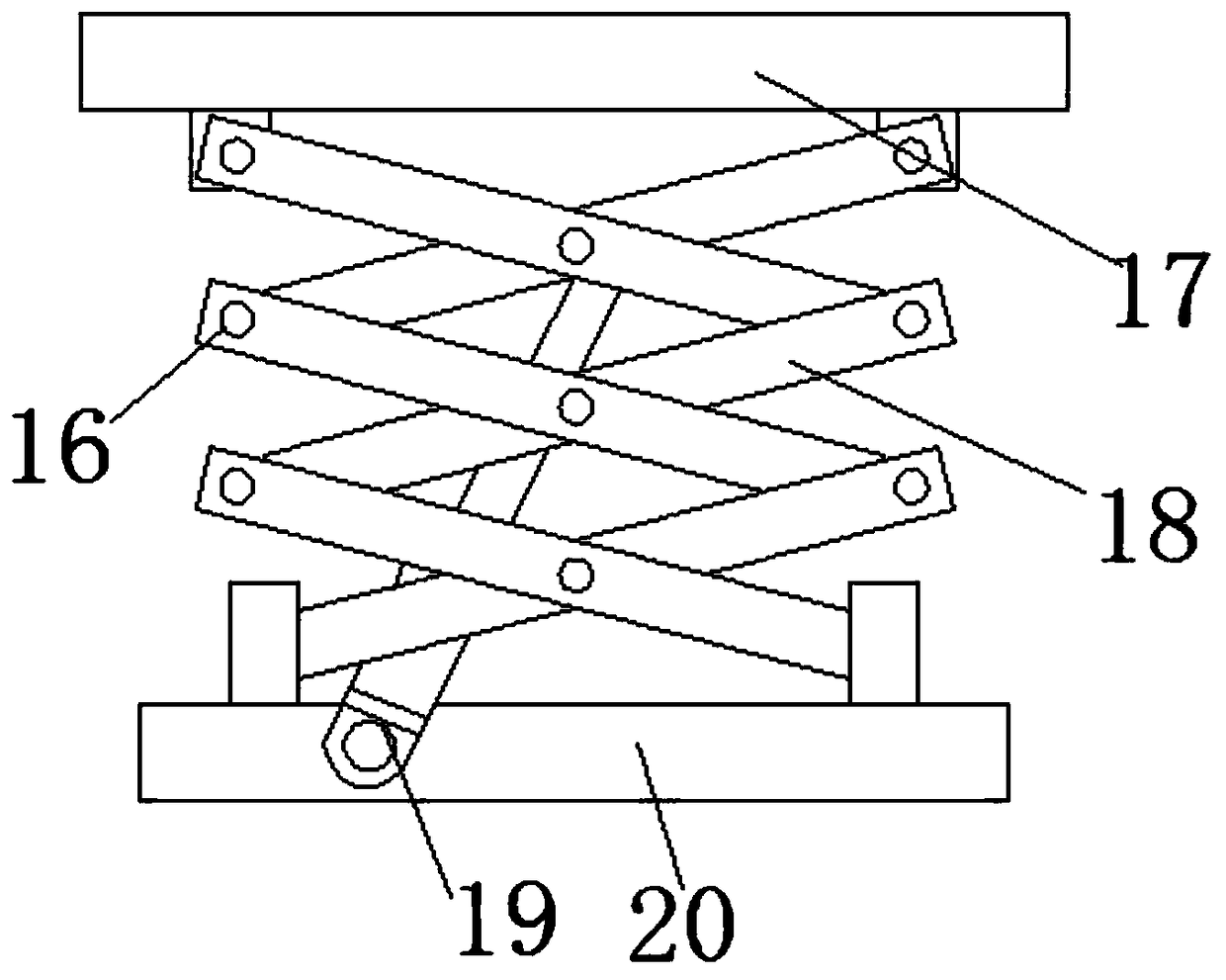
[0018] see Figure 1-2 , the present invention provides a technical solution: a tire frame adjustment seat for shipbuilding, including a mounting seat 3, a hydraulic lifting platform 2 is fixedly connected inside the mounting seat 3, and a bottom plate 20 is horizontally fixed at the bottom of the hydraulic lifting platform 2 , the top of the hydraulic lifting platform 2 is provided with a top plate 17, and movable rods 18 are interlaced between the top plate ...


PUM


Abstract

The invention discloses a mold frame adjusting seat for boat building. The mold frame adjusting seat comprises an installation seat, wherein the interior of the installation seat is fixedly connectedwith a hydraulic lifting platform, the bottom end of the hydraulic lifting platform is horizontally fixedly provided with a bottom plate, the top end of the hydraulic lifting platform is provided witha top plate, movable rods are alternately arranged between the top plate and the bottom plate, the middle of the top plate is provided with an installation frame, two sides of the installation frameare symmetrically provided with a fixed plate, the inner side of the fixed plate is horizontally provided with a first hydraulic cylinder, one end of the first hydraulic cylinder is connected with anangle adjusting rod, a gear strip is integrally molded on the upper end surface of the angle adjusting rod, a first adjusting gear is arranged above the gear strip, and a second adjusting gear is arranged between the first adjusting gear and the gear strip. By virtue of the angle adjusting rod and the first adjusting gear, the first hydraulic cylinder controls the movement of the angle adjusting rod along the horizontal direction, so that the angle of a supporting rod is changed by virtue of the first adjusting gear engaged with the second adjusting gear, and the adjusting precision can be improved.

Description

technical field [0001] The invention relates to the technical field of shipbuilding equipment, in particular to a tire frame adjustment seat for shipbuilding. Background technique [0002] The tire frame is a special process equipment for the convenience of mechanical equipment assembly and welding. Different equipment and different processes have different forms of tire frames. The tire frame for the hull is a special equipment for the assembly and welding of the hull sections. Its working surface should fit the section shape. Its function is to make the assembly and welding work of the sections have good conditions. The commonly used The tire frame structure is generally welded by section steel. The commonly used tire frame structure is generally formed by assembling and welding various steel profiles and templates, which cannot meet the manufacturing requirements, nor can it be disassembled and adjusted again. It is often remade after dismantling. This causes a lot of ...

Claims


Application Information

Patent Timeline
Patent Type & Authority Applications(China)
IPC IPC(8): B63C5/02B63B9/00
CPCB63B71/00B63C5/02
Inventor 王正阳
Owner 芜湖籁余新能源科技有限公司
Learn More