a cutting device

A technology of cutting device and connecting rod, which is applied in the field of mechanical processing, can solve the problems such as the inability to automatically push the plate and the inability to ensure the consistent cutting length of the plate, so as to achieve the effect of ensuring the consistent cutting length

Active Publication Date: 2020-07-28
宁波辉励铭诚汽车零部件有限公司
View PDF6 Cites 1 Cited by
  • Summary
  • Abstract
  • Description
  • Claims
  • Application Information

AI Technical Summary

Problems solved by technology

[0004] The present invention intends to provide a cutting device to overcome the problems in the prior art that the plate cannot be automatically pushed and the cutting length of the plate cannot be guaranteed to be consistent

Method used


Image

  • a cutting device
  • a cutting device

Examples


Embodiment Construction

[0015] The present invention will be described in further detail below by means of specific embodiments:

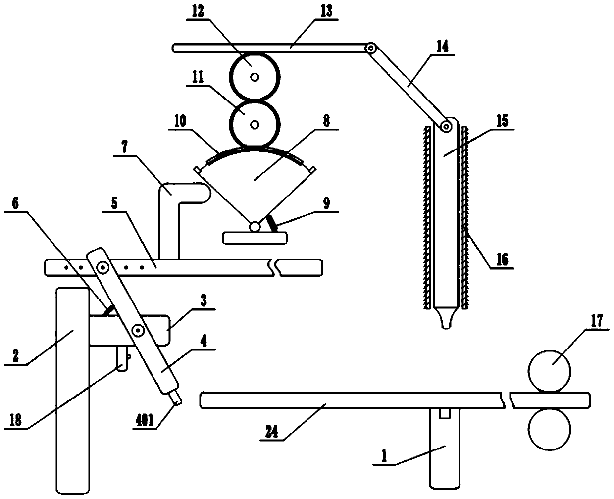
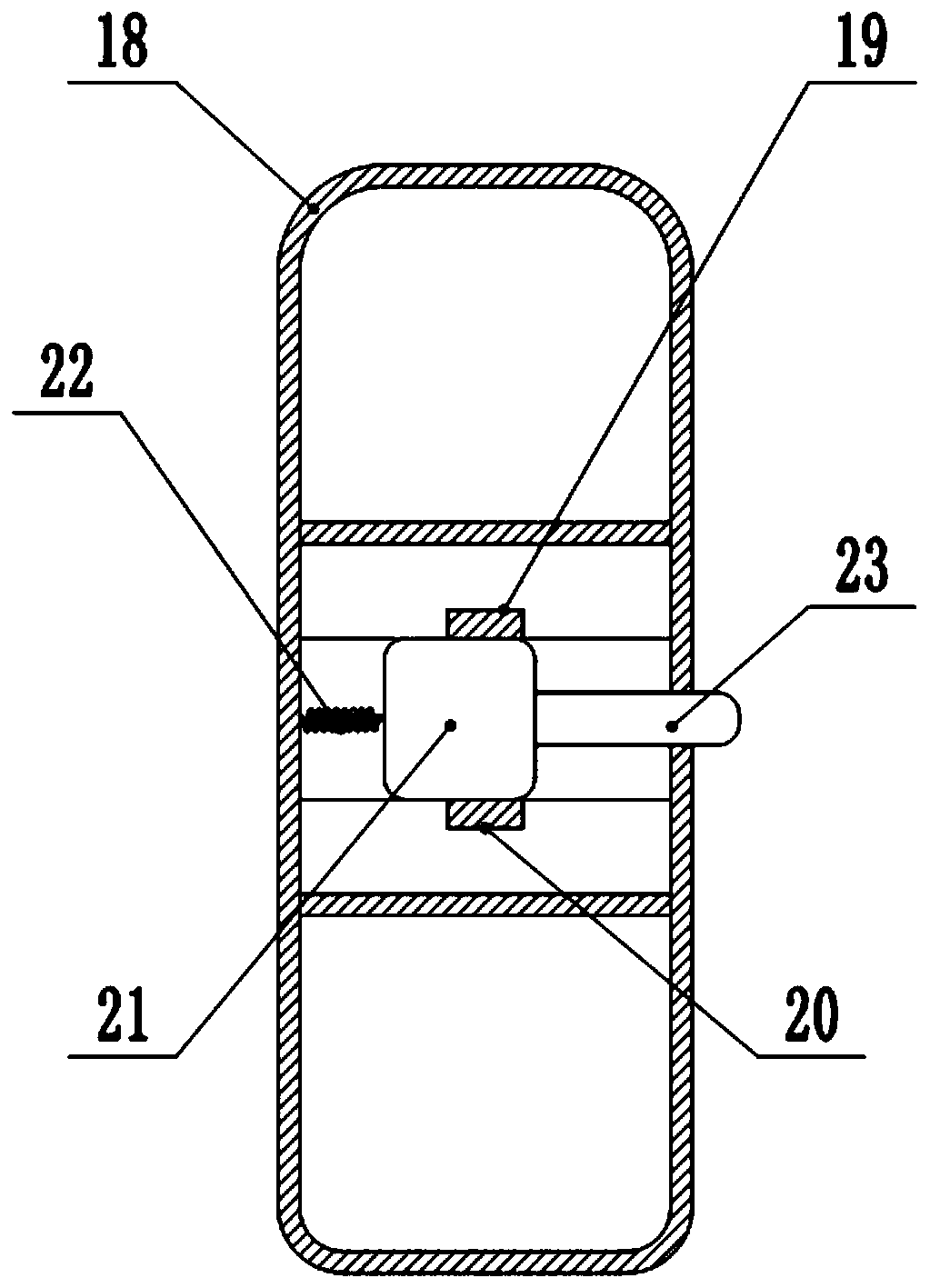
[0016] The reference signs in the accompanying drawings of the description include: support platform 1, support column 2, support rod 3, first connecting rod 4, toggle piece 401, push plate 5, extension spring 6, push rod 7, fan-shaped swing plate 8, The first spring 9, the first rack 10, the first wheel 11, the second wheel 12, the second rack 13, the second connecting rod 14, the slide bar 15, the limit tube 16, the conveying assembly 17, the switch body 18. The first contact piece 19 , the second contact piece 20 , the conductive block 21 , the second spring 22 , the pressing rod 23 , and the plate 24 .

[0017] The embodiment is basically as attached figure 1 , attached figure 2 Shown: a cutting device, including a frame, a support platform 1, a support column 2, the support column 2 is fixedly connected with a horizontally arranged support rod 3, the support rod 3...


PUM


Abstract

The invention relates to the technical field of machining, and discloses a cutting device. The cutting device comprises a frame, a support platform and a support column. The support column is fixedlyconnected with a support rod, the support rod is hinged with a first connecting rod, and the lower end of the first connecting rod is provided with a poking piece. A power switch is arranged at the lower end of the support rod, and a pushing plate is hinged at the upper end of the first connecting rod. A fan-shaped swinging plate is hinged on the frame, and a pushing rod is arranged on the surfaceof the pushing plate. A first spring is connected between the fan-shaped swinging plate and the frame, the circular arc edge of the fan-shaped swinging plate is in sliding connection with a first rack, and two ends of the circular arc edge of the fan-shaped swinging plate are provided with limiting blocks. The upper surface of the first rack is engaged with a first rotating wheel, the first rotating wheel is engaged with a second rotating wheel, and the second rotating wheel is engaged with a second rack. One end of the second rack is hinged with a second connecting rod, the lower end of thesecond connecting rod is hinged with a cutting assembly, and one side of the support platform is provided with a conveying assembly. The cutting device has the advantage that plates can be pushed automatically, and the plate cutting length is consistent.

Description

technical field [0001] The invention relates to the technical field of machining, in particular to a cutting device. Background technique [0002] In the process of mechanical equipment processing, the cutting of the plate is usually involved, and the long plate is cut into the required size according to the production demand, so as to carry out the next production process; the existing cutting equipment is usually used in the cutting process. Manually push the board to the cutting knife, and then cut the board. Manually pushing the board can not ensure that the length of the board is consistent each time, so that the length of the cut board does not meet the production requirements, which directly affects the cutting quality of the board. [0003] Therefore, how to automatically push the sheet so that the cutting length of the sheet is consistent each time is an urgent problem to be solved now. Contents of the invention [0004] The present invention intends to provide a...

Claims


Application Information

Patent Timeline
Patent Type & Authority Patents(China)
IPC IPC(8): B26D1/18B26D7/06B23D15/06B23D33/02
CPCB23D15/06B23D33/02B26D1/18B26D7/06
Inventor 柯烨
Owner 宁波辉励铭诚汽车零部件有限公司
Why Eureka
Try Eureka