Sectional material cleaning method and cleaning device
A technology for cleaning equipment and profiles, applied in the direction of using liquid cleaning methods, cleaning methods and utensils, chemical instruments and methods, etc., can solve the problems of inability to realize continuous work of production stations, unfavorable profile stability, easy deformation and bending, etc. Achieve the effect of saving cleaning manpower, various methods, and reducing pressure
- Summary
- Abstract
- Description
- Claims
- Application Information
AI Technical Summary
Problems solved by technology
Method used
Image
Examples
Embodiment 1
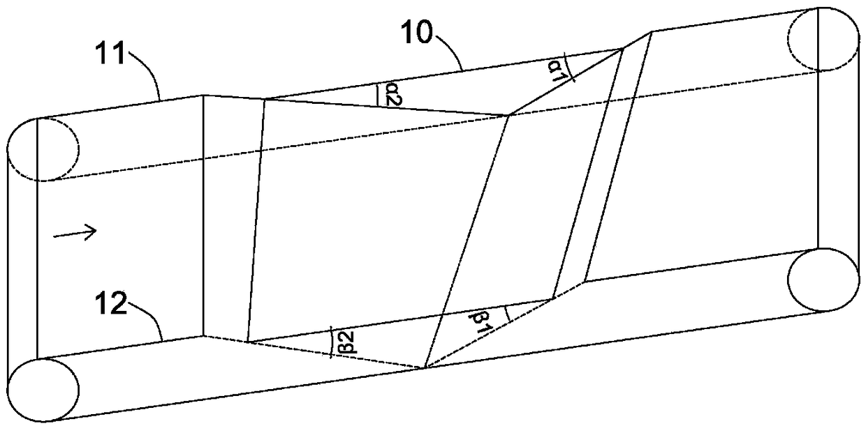
[0039] Such as figure 2 , 3 As shown, the conveying mechanism includes a first conveyor belt 11 and a second conveyor belt 12 arranged in parallel, and the first conveyor belt 11 and the second conveyor belt 12 respectively extend in and out through the cleaning tank 2 and leave the liquid surface A section of 10 forms unequal included angles α1 and β1 with the liquid surface respectively. Since the included angles α1 and β1 are not equal, the velocity components at both ends of the profile are different at the vertical height. The larger the included angle, the greater the velocity component, and the corresponding one end will reach the liquid surface faster than the other end.
[0040]The sections of the first conveyor belt 11 and the second conveyor belt 12 entering the liquid surface 12 form unequal angles α2 and β2 with the liquid surface 12 respectively. The principle is as above, using the different components of velocity in the vertical direction to achieve the effe...
Embodiment 2
[0044] Such as Figure 5-8 As shown, the conveying mechanism includes a pole 21 for supporting profiles, and a third conveyor belt 22 for driving the pole 21 to move, and the third conveyor belt 22 extends in and out through the cleaning pool; One end of the pole 21 extends freely, and the other end is connected to the third conveyor belt 22 after the hinged support 23; an adjustment mechanism for adjusting the angle between the pole 21 and the horizontal plane is also provided. The adjustment mechanism is a convex plate 24, which is arranged below the pole 21 and extends in the same direction as the third conveyor belt 22. The height of the section leaving the liquid front is greater than the support 23, and the height of the section entering the liquid front is smaller than the support 23. The free end of the support rod 21 is provided with a locking mechanism 25 for preventing the profile 4 from slipping.
[0045] When working, the profile can be inserted into the support ...
Embodiment 3
[0047] Such as Figure 9 As shown, the conveying mechanism includes a first boom 31 and a second boom 32 arranged in parallel, and a transmission mechanism 33 for driving the two booms through the feeding area, the cleaning tank and the discharging area in sequence; The two booms are suspended above the feeding area, cleaning pool and discharging area. The upper ends are respectively connected to the transmission mechanism 33, and the lower ends are free to extend downwards and are respectively provided with a clamping mechanism 34 for clamping the profile. The middle part is respectively provided with a length Adjustment mechanism 35 .
[0048] After the profile is clamped by the two booms, the relative distance between the two booms and the cleaning tank is realized through the length adjustment mechanism, thereby realizing the adjustment of the inclination angle of the profile. For example, in the process of conveying, the two clamping mechanisms in the feeding area stably...
PUM
 Abstract
Description
Claims
Application Information
 - R&D
- Intellectual Property
- Life Sciences
- Materials
- Tech Scout
- Unparalleled Data Quality
- Higher Quality Content
- 60% Fewer Hallucinations
Browse by: Latest US Patents, China's latest patents, Technical Efficacy Thesaurus, Application Domain, Technology Topic, Popular Technical Reports.
© 2025 PatSnap. All rights reserved.Legal|Privacy policy|Modern Slavery Act Transparency Statement|Sitemap|About US| Contact US: help@patsnap.com


