
Inflation and drainage device for spent fuel storage-transport vessel

A drainage device and spent fuel technology, applied in the field of nuclear containers, can solve problems such as no device has been developed

Inactive Publication Date: 2018-11-27
XI AN JIAOTONG UNIV +1
View PDF13 Cites 2 Cited by
  • Summary
  • Abstract
  • Description
  • Claims
  • Application Information

AI Technical Summary

Problems solved by technology

[0006] Existing research designs have not developed corresponding devices for the above realistic needs

Method used


Image

  • Inflation and drainage device for spent fuel storage-transport vessel
  • Inflation and drainage device for spent fuel storage-transport vessel
  • Inflation and drainage device for spent fuel storage-transport vessel

Examples


Embodiment Construction

[0019] The present invention will be further described below in conjunction with the accompanying drawings.

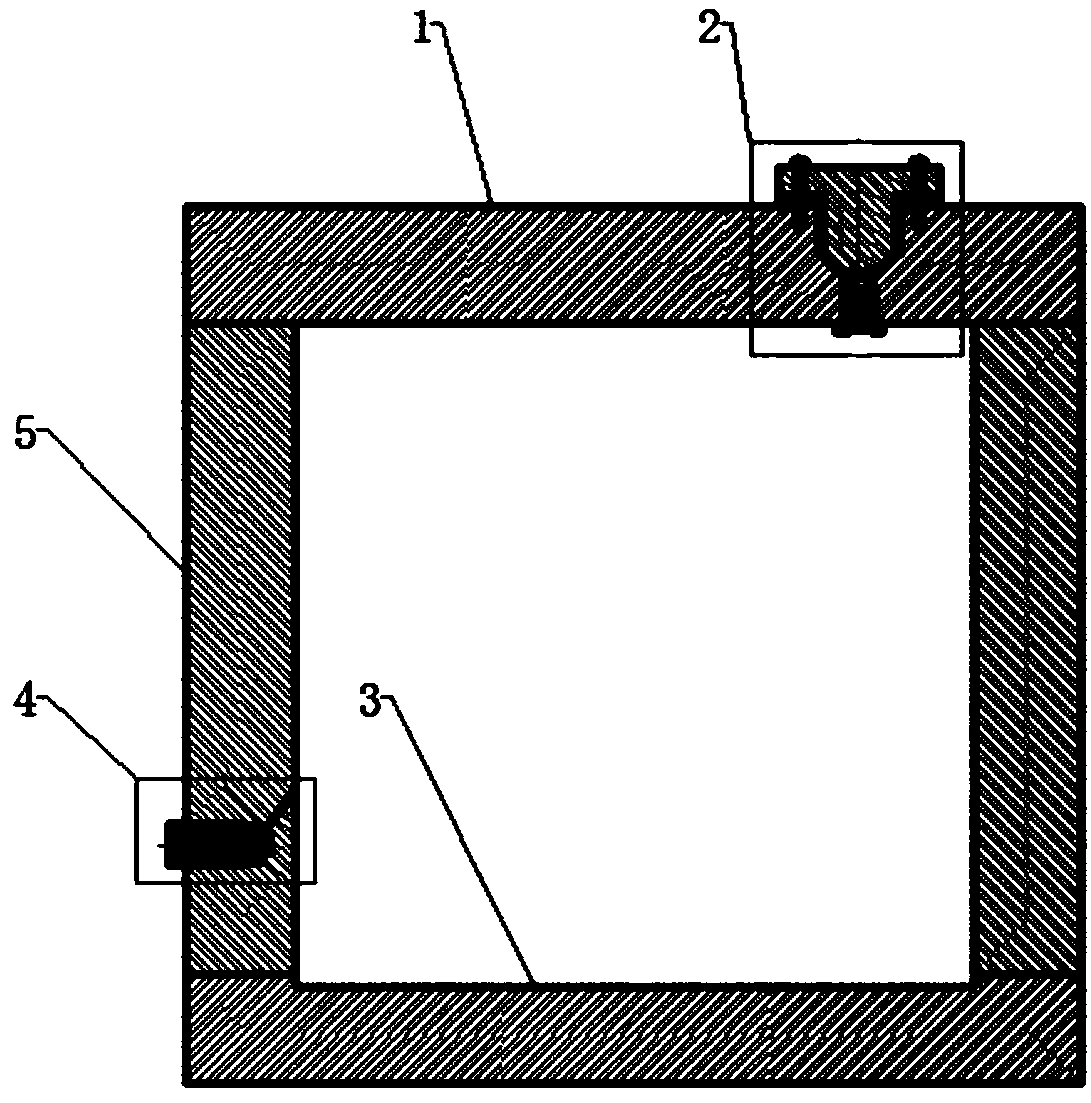
[0020] refer to figure 1 As shown, an inflation and drainage device for a spent fuel storage and transportation container includes a cylinder body 5, and the upper and lower ends of the cylinder body 5 are provided with a first cover plate 1 and a second cover plate 3; the air intake of the first cover plate 1 The port is provided with a shielding compensation plug and an inflation check valve structure 2; the cylinder body 5 is provided with a drain hole and a drain valve structure 4 near the bottom.

[0021] refer to figure 2 As shown, the shielding compensating plug and the inflation check valve structure 2 include a shielding compensating plug 8, the shielding compensating plug 8 is arranged at the air inlet of the first cover plate 1, and the shielding compensating plug 8 is connected to the first The cover plate 1 is provided with a check valve seat 12 under t...


PUM


Abstract

The invention provides an inflation and drainage device for a spent fuel storage-transport vessel. The device comprises a cylinder, wherein a first cover plate and a second cover plate are arranged atupper and lower ends of the cylinder; a shielding compensation plug and an inflation check valve structure are arranged at the air inlet of the first cover plate; and a draining hole and a draining valve structure are arranged close to the bottom of the cylinder. When the device is used, a spent fuel storage-transport vessel is inflated and drained by adopting the shielding compensation plug andinflation check valve structure and the draining hole and draining valve structure. The inflation and drainage device has the advantages of practicality, safety and reliability.

Description

technical field [0001] The invention relates to a nuclear container, in particular to an inflation and drainage device for a spent fuel storage and transportation container. Background technique [0002] Fuel assemblies in nuclear power plants need to be taken out of the reactor after they reach the burn-up depth. Because they are rich in radioactive substances, they are highly harmful. If they are not handled properly, they will cause serious environmental hazards and loss of life and property. The first step in the processing of spent fuel is usually to store it in the nearby nuclear power plant's boron water pool, where it needs to be kept for several years to cool it down. [0003] However, due to the continuous generation of spent fuel and the limited storage capacity of boron pools in nuclear power plants, it is necessary to transfer the spent fuel out of the pool in time to replace the storage location or enter reprocessing. However, my country's nuclear power constr...

Claims


Application Information

Patent Timeline
Patent Type & Authority Applications(China)
IPC IPC(8): G21C13/02F16K15/20F16K15/04
CPCF16K15/044F16K15/20G21C13/02Y02E30/30
Inventor 童琦琦胡海军王盛叶海盛培真李建仓
Owner XI AN JIAOTONG UNIV
Learn More