
Method for detecting axis parts and device thereof

A technology of shaft parts and detection methods, applied in the field of detection, can solve the problems of many human errors, difficulty in realizing high-precision product detection requirements, and inability to guarantee accuracy.

Pending Publication Date: 2018-11-27
GUANGZHOU UNIVERSITY
View PDF4 Cites 5 Cited by
  • Summary
  • Abstract
  • Description
  • Claims
  • Application Information

AI Technical Summary

Problems solved by technology

This traditional measurement method is highly dependent on labor, with a large amount of manual labor, low efficiency, unguaranteed accuracy, and many human errors, making it difficult to meet the detection requirements of high-precision products.
[0004] It can be seen that in the existing technology, the detection of parts relies on traditional detection methods, and the accuracy cannot be guaranteed.

Method used


Image

  • Method for detecting axis parts and device thereof
  • Method for detecting axis parts and device thereof
  • Method for detecting axis parts and device thereof

Examples


Embodiment Construction

[0074] The present invention is described in further detail below in conjunction with embodiment and accompanying drawing, but the embodiment of the present invention is not limited thereto.

[0075] Implementation one:

[0076] A method for detecting shaft parts, comprising the following steps:

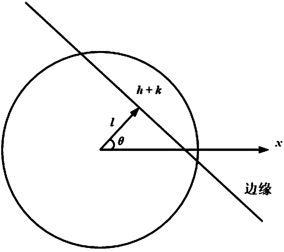
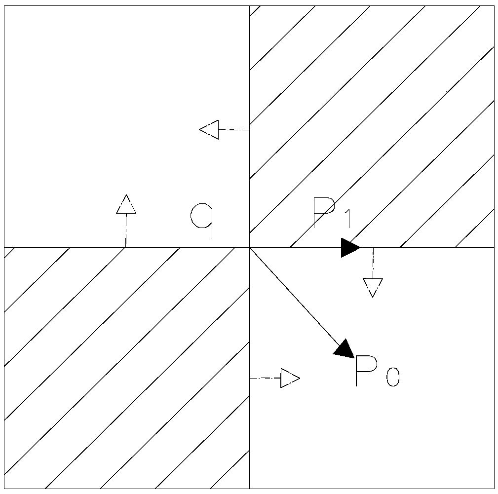
[0077] Image acquisition - image correction - sub-pixel edge detection - sub-pixel corner detection - image stitching - diameter detection

[0078] Step 1. Image Acquisition

[0079] Through the movement of the camera, the camera is used to take images of each part of the shaft parts to be detected that need to be detected.

[0080] Step 2. Image correction

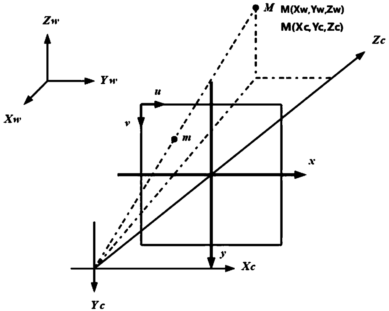
[0081] (1) Camera calibration

[0082] Calibration steps:

[0083] What the present invention selects for use is the chessboard grid as calibration plate. The calibration board is a 12×9 checkerboard grid, and the size of each grid is 20mm×20mm. Select an appropriate objective lens distance, and take multiple shots of the...


PUM


Abstract

The invention discloses a method for detecting axis parts and a device thereof. The device for detecting axis parts comprises a dark box, a workpiece conveying mechanism and image pickup mechanisms, wherein the workpiece conveying mechanism and the image pickup mechanism are arranged in the dark box. The number of the image pickup mechanisms is two, and the image pickup mechanisms are respectivelyoppositely arranged on two sides of a workpiece conveying direction of the workpiece conveying mechanism, and the image pickup mechanism comprises a camera and two light supplementing lamps. The twolight supplementing lamps are respectively arranged on both sides of the camera. The method and the device can detect radius, height, coaxial ratio, defect and the like of each part of axis parts, andcan automatically determine whether the processed axis parts is qualified or not.

Description

technical field [0001] The invention relates to the detection field, in particular to a method and device for detecting shaft parts. Background technique [0002] At present, the era of Industry 4.0 has quietly arrived. Based on this background, intelligent manufacturing is the theme of the world today, aiming to improve the intelligence level of the manufacturing industry and establish intelligent factories with adaptability and resource efficiency. In today's era, intelligent manufacturing undoubtedly has a broad market. [0003] Existing detection methods for shaft parts generally use traditional measuring tools such as centimeters, micrometers, vernier calipers, and screw micrometers for manual measurement. This traditional measurement method is highly dependent on manual work, with a large amount of manual labor, low efficiency, unguaranteed accuracy, and many human errors, making it difficult to meet the testing requirements for high-precision products. [0004] It c...

Claims


Application Information

Patent Timeline
IPC IPC(8): G06T7/00G06T7/13G06T7/80
CPCG06T7/0004G06T7/80G06T2207/30164
Inventor 伍冯洁林佳翰林佳苗黄成浩黄文恺吴羽何唐梅
Owner GUANGZHOU UNIVERSITY
Learn More