A self-generating large-range flow self-adjusting intelligent detection equipment

It is an intelligent detection and large-scale technology, which is applied in the direction of measuring flow/mass flow, liquid/fluid solid measurement, measuring devices, etc. It can solve the problems of inaccurate monitoring of flow, more parts of electronic control equipment, and unstable monitoring results. , to achieve stable and reliable flow monitoring, simple and stable signal processing, and improve monitoring accuracy

Active Publication Date: 2019-10-25
湖南欧柏测控系统有限责任公司 +3
View PDF8 Cites 0 Cited by
  • Summary
  • Abstract
  • Description
  • Claims
  • Application Information

AI Technical Summary

Problems solved by technology

The current water flow monitoring meters all use traditional flow meters or flow water meters, but there is a defect in the existing flow meters or flow water meters. When the flow in the pipeline fluctuates greatly, it is limited to the existing flow meter impeller structure. As a result, the flow cannot be accurately monitored, making the measurement results inaccurate
At present, in order to solve this problem, a bypass branch is installed on the pipeline, a large flow meter and an electric control valve are installed on the main pipe, and a small flow meter and an electric control valve are installed on the bypass branch, and then flow meters of different sizes are used to cooperate. The solenoid valve controls the electric control valve to open the main pipe or the bypass branch pipe according to the flow rate to realize accurate flow monitoring. This method not only complicates the pipeline setting, but also has high cost. At the same time, due to the increase of electronic control equipment parts, the circuit stability is poor and the monitoring results are also poor. Unstable and prone to failure

Method used


Image

  • A self-generating large-range flow self-adjusting intelligent detection equipment
  • A self-generating large-range flow self-adjusting intelligent detection equipment
  • A self-generating large-range flow self-adjusting intelligent detection equipment

Examples


Embodiment Construction

[0032] In order to enable those skilled in the art to better understand the technical solutions of the present invention, the present invention will be described in detail below with reference to the accompanying drawings. The description in this section is only exemplary and explanatory and should not have any limitation on the scope of protection of the present invention. .

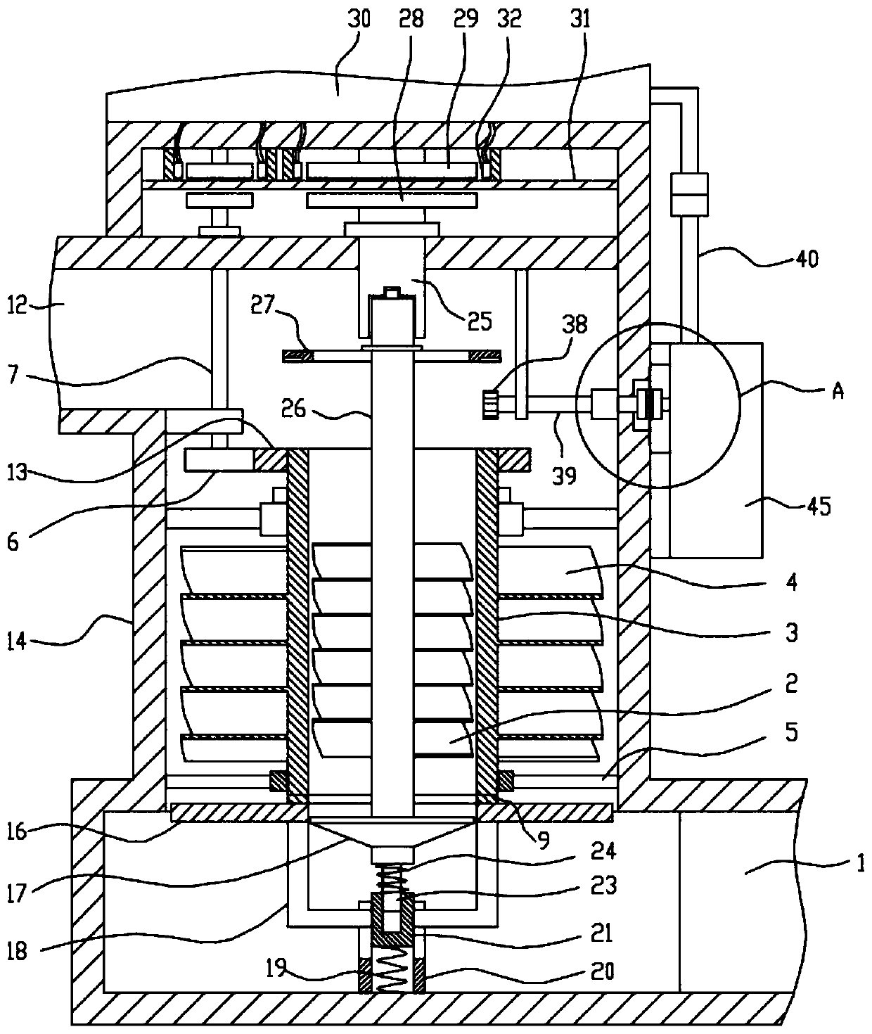
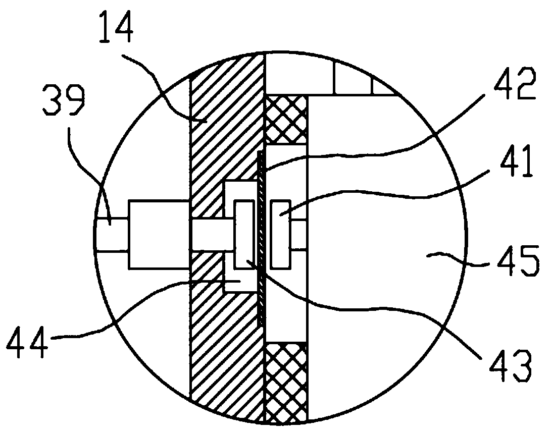
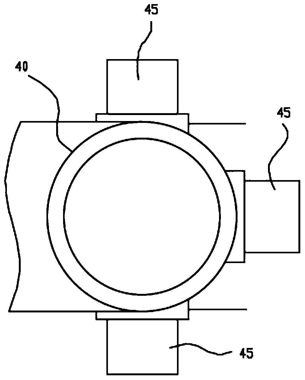
[0033] Such as Figure 1-Figure 12 As shown, the specific structure of the present invention is: a self-powered large-range flow rate self-adjusting intelligent detection device, which includes a mounting cavity 14, the top side of the mounting cavity 14 is provided with a water inlet 12, and the lower side is provided with an outlet Nozzle 1, the installation cavity 14 is vertically provided with an outer impeller 4; the center of the outer impeller 4 is provided with a sleeve shaft 3; the sleeve shaft 3 is coaxially provided with an inner impeller 2; the sleeve shaft 3 is provided with a lower gear ring...


PUM


Abstract

The invention discloses self power generation type wide range flow self-adjusting intelligent detection equipment. An outer impeller is arranged in a mounting cavity, a sleeve shaft is arranged in thecenter of the outer impeller and internally provided with an inner impeller, a lower gear ring is arranged at the lower end of the sleeve shaft, an annular gear is arranged at the upper end of the sleeve shaft, and the annular gear is meshed with a driven gear; a rotating shaft is arranged in the center of the inner impeller, a water plugging cover is arranged at the lower end of the rotating shaft, a thin shaft is arranged at the lower end of the water plugging cover, the lower end of the thin shaft is sleeved with a lifting cylinder, a connecting rod is arranged on the outer wall of the lifting cylinder and connected with a water plugging ring, and a bottom gear ring is arranged on the upper end face of the water plugging ring; the lifting cylinder is arranged in a fixing cylinder whichis provided with a clamping groove; a gear pressure plate is arranged at the upper end of the rotating shaft, a transmission gear is arranged on the lower portion of the gear pressure plate and connected with a driving shaft, and the driving shaft is connected with an electric generator from a distance through magnetic attraction. Accordingly, the high water flow rate and the low water flow ratecan be monitored simultaneously, the application range is wide, self-generation can be achieved, power generation and flow monitoring are subjected to individual drive, the monitoring result is accurate, and energy consumption is very low.

Description

Technical field [0001] The invention relates to the technical field of intelligent monitoring instruments, in particular to a self-generating large-range flow self-adjusting intelligent detection equipment. Background technique [0002] Intelligent instrumentation refers to instruments and meters used in discrete manufacturing and process industrial equipment to continuously measure variables such as temperature, pressure, flow, and level, or to measure physical parameters such as object position, tilt, and rotation, and material composition. Including sensors and their systems, smart temperature, pressure, flow, level measuring instruments, smart meters, smart water meters, and other monitoring devices. Current water flow monitoring meters use traditional flow meters or flow meters, but the existing flow meters or flow meters have a defect. When the flow in the pipeline fluctuates greatly, it is limited to the existing flow meter impeller structure. As a result, the flow cannot...

Claims


Application Information

Patent Timeline
Patent Type & Authority Patents(China)
IPC IPC(8): G01F1/115
CPCG01F1/115
Inventor 徐少华许长富何丹廖长安
Owner 湖南欧柏测控系统有限责任公司
Why Eureka
Try Eureka