
Vaneless fan lamp

A bladeless fan and lamp holder technology, which is applied to lighting devices, machines/engines, lighting device components, etc., can solve the problems of small wind receiving area, single function, and difficult cleaning

Inactive Publication Date: 2018-11-27
吴利华
View PDF0 Cites 5 Cited by
  • Summary
  • Abstract
  • Description
  • Claims
  • Application Information

AI Technical Summary

Problems solved by technology

[0003] The invention aims to solve many problems of the existing products such as single function, fixed wind direction, small wind receiving area, difficult cleaning, certain hidden safety hazards, and relatively large restrictions on the use space of the product.

Method used


Image

  • Vaneless fan lamp
  • Vaneless fan lamp
  • Vaneless fan lamp

Examples


Embodiment 1

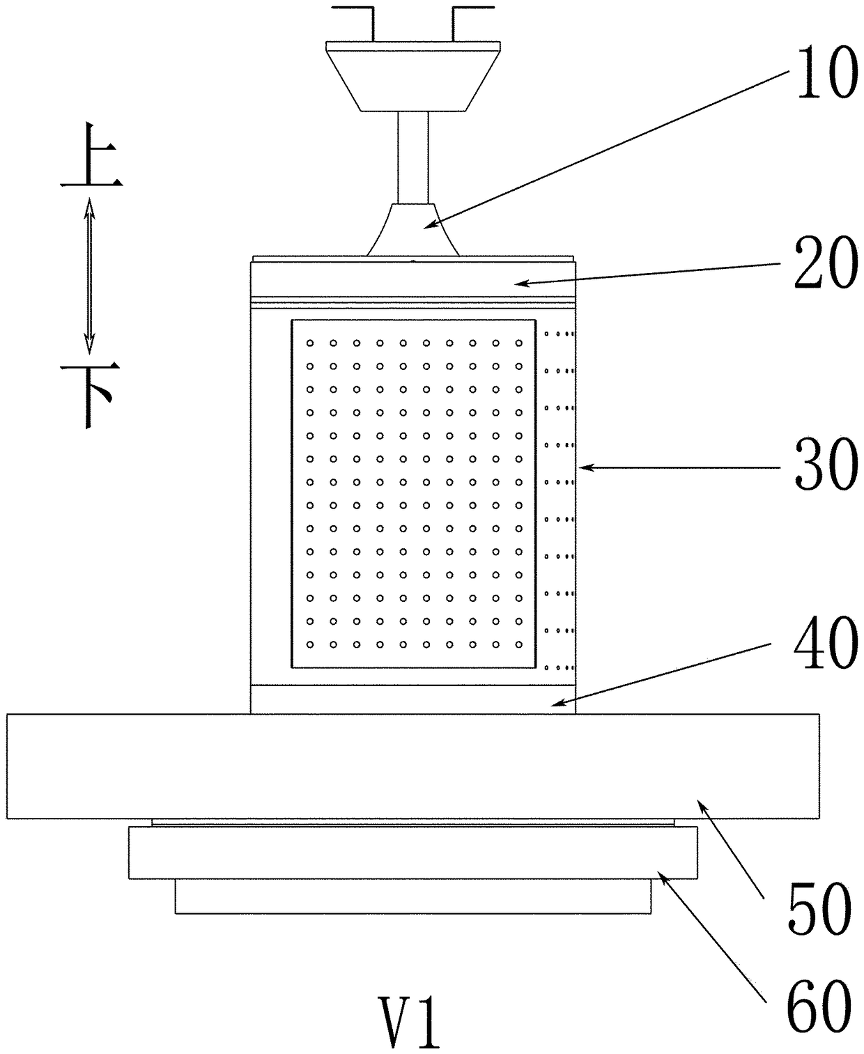
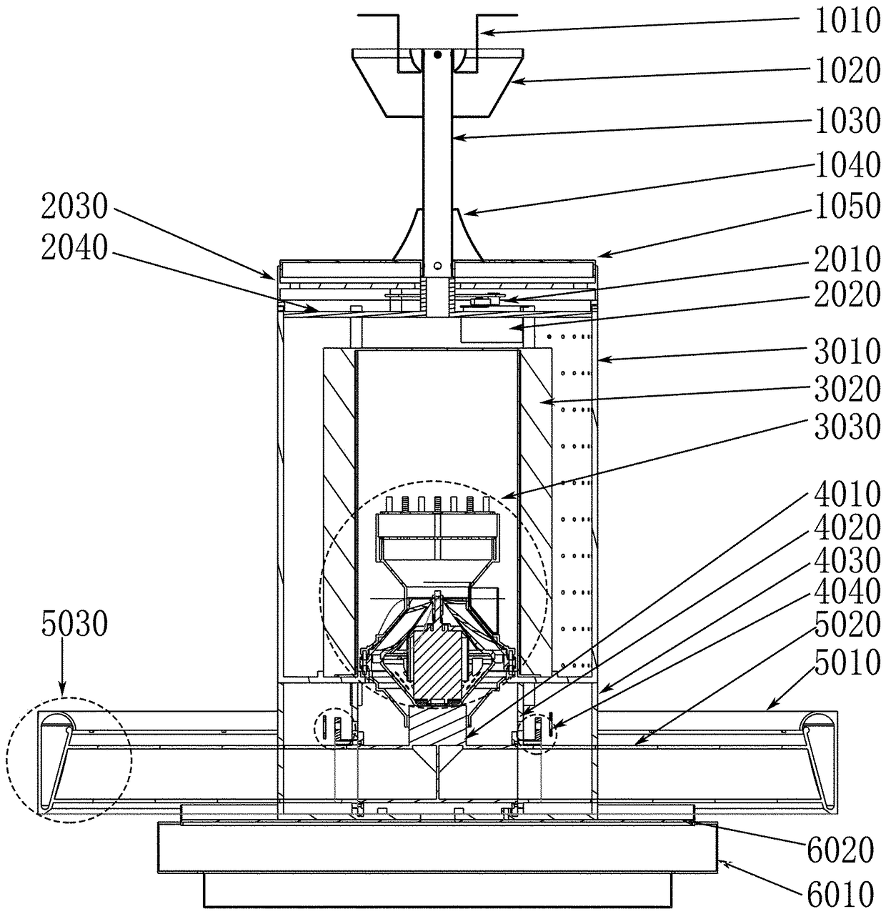
[0047] Such as image 3 and Figure 4 As shown, the fixing device 10 includes a fixing bracket 1010 , a large hanging cup 1020 , a hanging rod 1030 , a small hanging cup 1040 and a fixing plate 1050 . There are holes on the fixing bracket 1010, which can be fixed on the roof ceiling, wall or other required positions with screws or screws. The suspension rod 1030 is a hollow tube, its upper end is connected with the fixed bracket 1010 , and its lower end is connected with the fixed plate 1050 . There are screw holes around the fixed plate 1050 for fixing the base 20 on the fixed plate so as to position the body 30 . The large hanging cup 1020 is used to cover the connection between the fixed bracket 1010 and the suspender 1030, and the small hanging cup 1040 is used to cover the connection between the suspender 1030 and the fixed plate 1050, so that the overall appearance of the bladeless fan lamp V1 is neat and beautiful.

Embodiment 2

[0049] The length of the boom 1030 can be adjusted to be suitable for different usage spaces.

Embodiment 3

[0051] Screw holes are also provided on the fixing plate 1050. In one embodiment of the present invention, the fixing bracket 1010 and the suspender 1030 may not be used, and the fixing plate 1050 may be directly fixed to the roof ceiling or the wall with screws or screws. or other desired locations.


PUM


Abstract

The invention discloses a vaneless fan lamp, which comprises a fixing device, a base, a body, a machine head, an air outlet part and a lighting part, wherein, the vaneless fan lamp comprises a fixingdevice, a base, a body, a machine head, an air outlet part and a lighting part. The fixing device is used for fixing the vaneless fan lamp, the base is used for realizing the reciprocating rotation ofthe vaneless fan lamp around the axis, and the power device and other functional components are accommodated in the machine body for realizing the functions of air purification and air heating, etc.The power device in the machine body is used for generating high-pressure air flow, and the high-pressure air flow is guided to the three-way structure in the machine head. The high-pressure air flowentering the three-way structure is guided to the air outlets through the two outlets of the three-way structure. The two high-pressure air streams are ejected from the air outlet of the air outlet part under the action of the high pressure to generate a high-speed air stream. High-speed air currents can drive the surrounding air to flow together to generate wind power. A light part is mounted onthat low part of the machine head, and the lighting part includes a light source, so that the function of luminous lighting can be realized.

Description

technical field [0001] The invention relates to the field of household electrical appliances, in particular to a bladeless fan lamp with lighting function. Furthermore, on this basis, one or more of the following functions can be added as needed, such as heating function, air purification function, negative oxygen ion function, mosquito killing function, air humidification function, aromatherapy function, etc. Background technique [0002] The fan is a commonly used household electrical appliance, and the lamp is also an indispensable electrical appliance in people's daily life. Now there are bladed fan lamps that combine lamps and fans on the market. The blades of this type of product are exposed to the outside, and the motor rotates to drive the blades to rotate, so that the air circulates and generates wind force to achieve the purpose of cooling. Because the blades are exposed to the outside, the blades rotate at high speed when the product is running, so there are cer...

Claims


Application Information

Patent Timeline
IPC IPC(8): F04F5/16F04F5/44F21V33/00
CPCF04F5/16F04F5/44F21V33/0096
Inventor 吴利华
Owner 吴利华
Learn More