
A multi-stage constant-pressure compressed air energy storage device

A technology of compressed air energy storage and compression tube, which is applied in pump devices, mining devices, non-variable capacity pumps, etc. Efficiency optimization and improvement, less energy consumption, and higher requirements

Active Publication Date: 2018-11-27
CHINA UNIV OF MINING & TECH
View PDF7 Cites 12 Cited by
  • Summary
  • Abstract
  • Description
  • Claims
  • Application Information

AI Technical Summary

Problems solved by technology

[0004] Large-scale compressed air energy storage power plants have high requirements on the volume of the gas storage chamber, and the high manufacturing cost of the gas storage tank has become a constraint that limits the development of energy storage technology
In addition, the existing gas storage containers for compressed air energy storage are all fixed volumes. As the amount of compressed air decreases, the output pressure will become smaller and smaller, and constant pressure gas transmission cannot be guaranteed, resulting in unstable power generation. It is difficult; secondly, when storing and using energy, the power required for different periods is different. The existing technology requires the compressor or the generator to work completely regardless of the demand, and the power settings of the compressor and the generator It must be able to meet the use requirements of the maximum demand, so when the power consumption is not large, it will lead to an increase in wasted power; when using high-voltage storage energy, the sealing and strength of the storage space are required to be high, and under high-voltage conditions As the temperature changes, the energy loss increases; when the pressure is low, there are problems of low energy density and limited adjustable power

Method used


Image

  • A multi-stage constant-pressure compressed air energy storage device
  • A multi-stage constant-pressure compressed air energy storage device
  • A multi-stage constant-pressure compressed air energy storage device

Examples


Embodiment Construction

[0025] In order to make the object, technical solution and advantages of the present invention clearer, the present invention will be further described in detail below in conjunction with specific embodiments and with reference to the accompanying drawings.

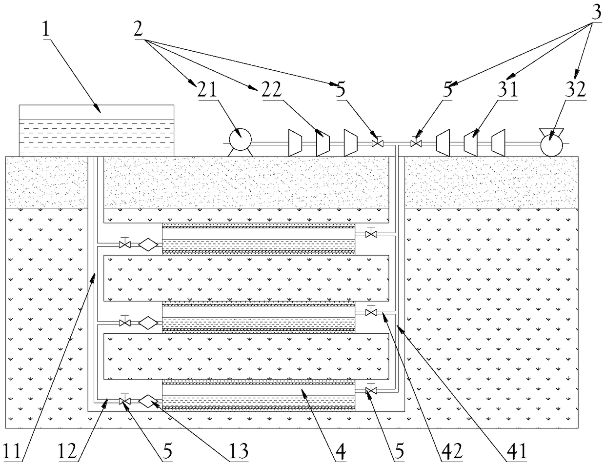
[0026] Such as figure 1 As shown, a multi-stage constant pressure compressed air energy storage device includes a water storage tank 1, a compression pipeline 2, a power generation pipeline 3 and at least two storage chambers 4 with height differences along the vertical direction; the water storage There is a height difference between the pool 1 and the storage chamber 4 in the vertical direction, and the reservoir 1 is connected to the storage chamber 4 through a water pipe 11 arranged downwards, thereby providing different water pressures for the storage chamber 4 at different heights; each storage chamber 4 The upper part is connected to the water pipe 11 through the water distribution pipe 12, and each water distribut...


PUM


Abstract

The invention discloses a multi-stage constant-pressure compressed air energy storage device, which comprises a water storage tank, a compression pipeline, a power generation pipeline and at least twostorage chambers with height difference along a vertical direction. A height difference exists between the storage tank and the storage chamber along the vertical direction; The storage tank is downwardly connected to each storage chamber through a water pipe, and each storage chamber is also respectively connected to a compression pipeline capable of compressing and storing air in the storage chamber and a power generation pipeline capable of discharging air in the storage chamber for power generation through the power generation pipeline. The invention provides a multi-stage constant-pressure compressed air energy storage device, which has the advantages that the output pressure is constant, the multi-stage pressure storage improves the energy utilization rate, the low-pressure high-efficiency storage improves the system efficiency, the storage chamber is stable and easy to control, and has good popularization prospect.

Description

technical field [0001] The invention relates to the technical field of energy storage and power generation, in particular to a multi-stage constant-pressure compressed air energy storage device. Background technique [0002] Electric energy storage refers to the process of storing electricity through media or equipment and releasing it when needed. Power energy storage technology is a key technology to solve the large-scale intervention of renewable energy and the problem of "abandoning wind and light"; it is an essential technology for the development of distributed energy, smart grid, and energy Internet; An important supporting technology for conventional energy generation efficiency and transmission efficiency, safety and economy. Electric energy storage technology can increase the ratio of clean energy power generation, and then realize the clean and efficient use of fossil energy, effectively reduce the emission of pollutants, and play a great role in the governance o...

Claims


Application Information

Patent Timeline
Patent Type & Authority Applications(China)
IPC IPC(8): F04D25/16F04D25/06F01D15/10E21F17/16
CPCE21F17/16F01D15/10F04D25/06F04D25/163
Inventor 张凯邓康宇薛欣然
Owner CHINA UNIV OF MINING & TECH
Learn More