
Turbogenerator compound condensate thermodynamic system

A steam turbine generator, thermal system technology, applied in engine components, machines/engines, mechanical equipment, etc., can solve problems such as affecting the surrounding environment, workers' health, and water waste.

Inactive Publication Date: 2018-11-27
黄均杰
View PDF0 Cites 0 Cited by
  • Summary
  • Abstract
  • Description
  • Claims
  • Application Information

AI Technical Summary

Problems solved by technology

[0002] Steam turbine is the main equipment of modern thermal power plants. Not only that, it is also widely used in metallurgy, shipbuilding and other industrial fields. In the use of steam turbines, most of the surrounding environment is poor, and the steam exhaust equipment is easy to become harmful when it encounters cold air. Metal sewage, thus affecting the surrounding environment and the health of workers, also caused a waste of water resources to a certain extent, so the advent of this invention can effectively solve this problem

Method used


Image

  • Turbogenerator compound condensate thermodynamic system
  • Turbogenerator compound condensate thermodynamic system

Examples


Embodiment Construction

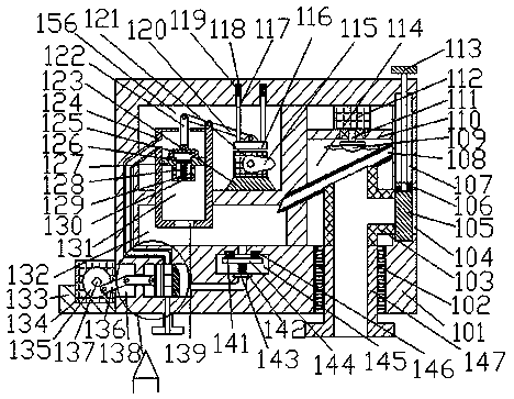
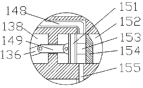
[0014] Such as figure 1 and figure 2As shown, the steam turbine generator composite condensate thermal system of the present invention includes a frame body 101 and a water storage chamber 132 extending left and right inside the frame body 101. A pumping chamber 156 is provided above the water storage chamber 132. The right side of the pumping chamber 156 is provided with a cooling chamber 114 extending up and down, and the cooling chamber 114 is provided with a condensing water collecting pipe 108 inclined downward to the left, and the left end corner of the condensing water collecting pipe 108 extends into the water storage chamber 132, the bottom end of the cooling chamber 114 is connected with a threaded port 102 extending up and down, and the threaded port 102 is threadedly connected with a threaded pipe 147 extending up and down and extending out of the bottom end of the frame body 101. The threaded pipe 147 The top end surface is provided with a top end extending into...


PUM


Abstract

The invention discloses a turbogenerator compound condensate thermodynamic system. The system comprises a shelf body and a water storage chamber arranged in the shelf body and extending left and right, characterized in that: A suction cham is arranged above that wat storage chamber, a temperature reduce chamber which extends upward and downward is arranged on that right side of the water pumping cham, the cooling chamber is provided with a left downward inclined condensing water collecting pipe, A left end angle of that condense water collect pipe extends into the water storage chamber, At that bottom end face of the temperature reduce cavity, a screw opening extend upward and downward is communicated, the screw opening is threadably connected with a screw pipe extend upward and downward and the bottom end of the screw pipe protrudes out of the rack body, the top end face of the screw pipe is provided with a top end protruding into the condensing water collecting pipe and a right end is provided with a diverting pipe rotating pipe; and at the bottom end face of the temperature reducing cavity, the screw pipe extends upward and the bottom end protrudes out of the rack body. The invention has the advantages of simple structure, short working period and obvious reflux effect.

Description

technical field [0001] The invention relates to the field of turbogenerators, in particular to a composite condensate thermal system of a turbogenerator. Background technique [0002] Steam turbine is the main equipment of modern thermal power plants. Not only that, it is also widely used in metallurgy, shipbuilding and other industrial fields. In the use of steam turbines, most of the surrounding environment is poor, and the steam exhaust equipment is easy to become harmful when it encounters cold air. Metal sewage affects the surrounding environment and the health of workers, and also causes waste of water resources to a certain extent. Therefore, the advent of this invention can effectively solve this problem. Contents of the invention [0003] The technical problem to be solved by the present invention is to provide a steam turbine generator composite condensate thermal system, which can solve the above-mentioned problems in the prior art. [0004] The present inventi...

Claims


Application Information

Patent Timeline
IPC IPC(8): F01D25/32
CPCF01D25/32
Inventor 何志辉
Owner 黄均杰
Learn More