
Water suction pump driven by tap water pressure

A technology of tap water and water pumps, applied in the direction of driving pumps, pumps, non-variable pumps, etc., can solve problems such as waste of hot water and heat energy, and achieve the effect of saving electric energy

Inactive Publication Date: 2016-07-06
中山浩发节能科技有限公司
View PDF7 Cites 0 Cited by
  • Summary
  • Abstract
  • Description
  • Claims
  • Application Information

AI Technical Summary

Problems solved by technology

[0002] Existing people drain the hot water used for bathing directly, so that most of the heat energy of the hot water is directly wasted

Method used


Image

  • Water suction pump driven by tap water pressure

Examples


Embodiment Construction

[0012] The technical solution and beneficial effects of the present invention will be clearer and more definite by further describing the present invention in conjunction with the accompanying drawings.

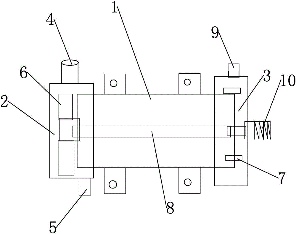
[0013] As shown in the figure, the present invention discloses a water pump driven by tap water pressure. Chamber 2 is provided with a water inlet 4 connected to the tap water pressure pipe and a water outlet 5 through which tap water flows away. In the water inlet pressure chamber 2, there is a driving impeller 6 that is driven by tap water pressure to rotate. In the pumping chamber 3, there is a The pumping impeller 7 is provided with a transmission shaft 8 connecting the driving impeller 6 and the pumping impeller 7 in the pump body 1 and drives the pumping impeller 7 to rotate in the pumping cavity 3 to realize the pumping function. Tap water enters from water inlet 4 like this, impacts driving impeller 6, and driving impeller 6 is rotated, drives pumping impeller 7 to ro...


PUM


Abstract

The invention discloses a water suction pump driven by tap water pressure. The water suction pump comprises a pump body, wherein a water inlet pressure cavity is arranged at one end of the pump body; a water suction cavity is arranged at the other end of the pump body; a water inlet connected to a tap water pressure pipe and a water outlet used for draining of tap water are arranged on the water inlet pressure cavity; a driving impeller which is pushed by the tap water pressure to rotate is arranged in the water inlet pressure cavity; a water suction impeller is arranged in the water suction cavity; and a transmission shaft is arranged in the pump body, connects the driving impeller with the water suction impeller, and drives the water suction impeller to rotate in the water suction cavity, so as to realize the water suction function. The water suction pump provided by the invention is simple in structure and driven by the tap water pressure.

Description

technical field [0001] The invention relates to a water pump driven by tap water pressure. Background technique [0002] Existing people directly discharge the used hot water after bathing, so that most of the heat energy of the hot water is directly wasted. When considering recycling the used hot water and reusing it, this case is a pump developed to pump up the used hot water and reuse it. Contents of the invention [0003] In order to overcome the deficiencies of the prior art, the invention provides a water pump driven by tap water pressure. [0004] The technical solution adopted by the present invention to solve its technical problems is: [0005] A water pump driven by tap water pressure, characterized in that it includes a pump body 1, a water inlet pressure chamber 2 is provided at one end of the pump body 1, a pumping chamber 3 is provided at the other end, and a water inlet pressure chamber 2 is provided on the water inlet pressure chamber 2. Connected to the...

Claims


Application Information

Patent Timeline
Patent Type & Authority Applications(China)
IPC IPC(8): F04D9/02
CPCF04D9/02
Inventor 覃维祥
Owner 中山浩发节能科技有限公司
Learn More