Novel coil upper positioning plate

A technology for positioning plates and coils, which is applied to household components, household appliances, and other household appliances. It can solve problems such as tilting, uneven pouring upper surface, time-consuming and labor-consuming, etc., to speed up the process, save manpower and time, Reduce the effect of post-processing work

Inactive Publication Date: 2018-11-27
JIANG SU ZHONGRONG TECH
View PDF4 Cites 0 Cited by
  • Summary
  • Abstract
  • Description
  • Claims
  • Application Information

AI Technical Summary

Problems solved by technology

This measurement method can only measure the liquid level height at a small part of the position, which is very easy to cause unevenness and inclination of the upper end surface of the pouring, which requires a lot of grinding, which is time-consuming and labor-intensive.

Method used


Image

  • Novel coil upper positioning plate

Examples


Embodiment Construction

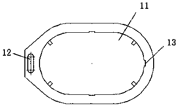
[0011] The present invention will be further explained below in conjunction with the drawings.

[0012] Such as figure 1 As shown, a novel coil upper positioning plate of the present invention includes a body 1 on which a pouring hole 11 and a measuring hole 12 are provided, and the measuring hole 12 is located on the left side of the pouring hole 11. A number of measuring ports 13 are opened on the inner wall of the pouring hole 11, and the measuring ports 13 are rectangular.

[0013] The pouring hole 11 and the measuring hole 12 both have a waist-shaped structure, and the line between the centers of the two arc sides in the pouring hole 11 is perpendicular to the line between the centers of the two arc sides in the measuring hole 12.

[0014] There are three measuring openings 13 respectively corresponding to the two straight sides of the pouring hole 11 and the arc side on the right side.

[0015] The invention adopts peripheral openings to facilitate the measurement of the pourin...


PUM


Abstract

The invention discloses a novel coil upper positioning plate. The upper positioning plate includes a body. A pouring hole and a measuring hole are arranged in the body. The measuring hole is located on the left side of the pouring hole. A plurality of measuring ports are arranged in the inner wall of the pouring hole. The measuring ports are rectangular. The upper positioning plate fundamentally solves the defect that the upper end face of a coil is not flat after the pouring is completed, and reduces the post-processing work. The process is accelerated, the appearance of the product is better, manpower and time are saved, and the cost is reduced.

Description

Technical field: [0001] The invention relates to a novel upper coil positioning plate. Background technique: [0002] Conventional pouring dry change tooling equipment (measuring pouring liquid level) consists of opening a long hole on the upper positioning plate to regularly measure the liquid level at the location. This measurement method can only measure the height of the liquid level in a small part of the position, and it is extremely easy to cause the upper end of the pouring to be uneven and inclined, requiring a lot of grinding, and time-consuming and labor-intensive. Summary of the invention: [0003] The present invention provides a novel coil upper positioning plate in order to solve the above-mentioned problems in the prior art. [0004] The technical solution adopted by the present invention is: a new type of coil upper positioning plate, including a body, the body is provided with a pouring hole and a measuring hole, the measuring hole is located on the left side of...

Claims


Application Information

Patent Timeline
IPC IPC(8): B29C39/22B29C39/44B29L31/34
CPCB29C39/22B29C39/44B29L2031/34
Inventor 寻亚孙国平周波杨昆
Owner JIANG SU ZHONGRONG TECH
Why Eureka
Try Eureka