
Conductive nozzle for gas shielded welding

A technology of gas shielded welding and conductive nozzles, which is applied in the direction of electrode accessories and electrode characteristics, can solve the problems of affecting work progress, increasing production costs, and not replacing parts, so as to save processing costs, improve efficiency, and facilitate machining. Effect

Inactive Publication Date: 2018-11-27
NANTONG SHENGLIN GEER ELECTRONICS TECH CO LTD
View PDF0 Cites 0 Cited by
  • Summary
  • Abstract
  • Description
  • Claims
  • Application Information

AI Technical Summary

Problems solved by technology

[0002] The traditional conductive tip for welding has only one through hole in the middle, and the phenomenon of welding wire consolidation and through hole wear often occurs during use. Because some welding work requires continuous operation, the traditional conductive tip is often affected by the wear of the through hole. work progress, and the traditional conductive tip cannot be replaced after use and wear, which is easy to cause waste and increase production costs

Method used


Image

  • Conductive nozzle for gas shielded welding
  • Conductive nozzle for gas shielded welding
  • Conductive nozzle for gas shielded welding

Examples


Embodiment Construction

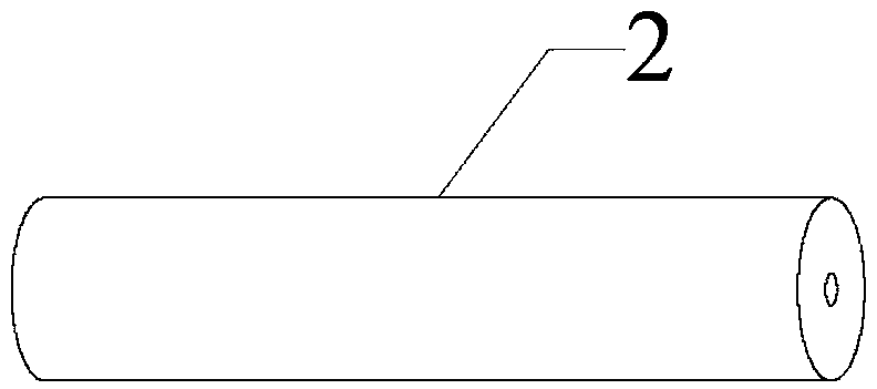
[0014] A conductive tip for gas shielded welding, comprising a conductive tip body 1, a through hole 11 is provided in the middle of the conductive tip body 1, and a cylindrical conductor 2 with a through hole in the axial direction, and a blind hole is provided at one end of the conductive tip body 1 12. The diameter of the blind hole 12 is larger than the diameter of the through hole 11, the blind hole 12 is coaxial with the through hole 11, the blind hole 12 and the through hole 11 form a stepped hole, and the cylindrical conductor 2 is mounted on In the blind hole 12, it matches with the blind hole 12 and is detachable.

[0015] The diameter of the through hole on the cylindrical conductor 2 is 4mm, and the axis direction of the conductive tip body 1 is provided with a dividing groove 13, and the length of the dividing groove 13 accounts for 8 / 9 of the total length of the conductive tip body 1, and the conductive tip body 1 The total length is 45 mm, and the length of the ...


PUM

PropertyMeasurementUnit
Diameteraaaaaaaaaa

Abstract

The invention relates to the technical field of welding tools, in particular to a conductive nozzle for gas shielded welding. The conductive nozzle comprises a conductive nozzle body and a cylindricalconductor. The middle of the conductive nozzle body is provided with a through hole, the cylindrical conductor is axially provided with a through hole, one end of the conductive nozzle body is provided with a blind hole, the diameter of the blind hole is larger than that of the through hole, the blind hole and the through hole are coaxial and form a step hole, and the cylindrical conductor is mounted in the blind hole and detachably matched with the blind hole. The conductive nozzle body is internally provided with the step hole, and by combination of the conductive nozzle body and the cylindrical conductor made of a C3604 brass material, resistance to welding wires is reduced, abrasion resistance is improved, welding efficiency is greatly improved, waste in welding is avoided, resourcesare saved, and production cost is reduced.

Description

technical field [0001] The invention relates to the technical field of welding tools, in particular to a conductive tip for gas shielded welding. Background technique [0002] The traditional conductive tip for welding has only one through hole in the middle, and the phenomenon of welding wire consolidation and through hole wear often occurs during use. Because some welding work requires continuous operation, the traditional conductive tip is often affected by the wear of the through hole. work progress, and the traditional conductive tip cannot be replaced after use and wear, which is easy to cause waste and increase production costs. Contents of the invention [0003] The technical problem to be solved by the present invention is how to overcome the deficiencies of the prior art and provide a conductive tip for gas shielded welding. [0004] The technical solution adopted by the present invention to achieve the above object is: a conductive tip for gas shielded welding,...

Claims


Application Information

Patent Timeline
IPC IPC(8): B23K9/26
CPCB23K9/26
Inventor 孙佳慧
Owner NANTONG SHENGLIN GEER ELECTRONICS TECH CO LTD
Learn More