


Quick Research
Generate reliable direction feasibility study reports for your R&D in just a few steps.

Technical Q&A
Discover and master advanced knowledge NOW. Basics, ideas, possibilities, all at once.

Find Solutions
As an expert in R&D theories, this can generate solutions to your technical problems instantly.

Evaluate Feasibility
Analyze your overall solution with one click, know your potential R&D risks in advance.

Monitor Landscape
Get weekly tech updates, stay abreast of the latest tech innovations and key insights.
Optical fiber unit and optical fiber cable
A technology of optical fiber unit and optical fiber bundle, applied in optical components, optics, light guide, etc., can solve the problem of fiber core wire breakage, etc., and achieve the effect of restraining twist
- Summary
- Abstract
- Description
- Claims
- Application Information
AI Technical Summary
Problems solved by technology
Method used
Image

Examples
no. 1 approach
[0052] (Evaluation of entanglement characteristics caused by binding parts)
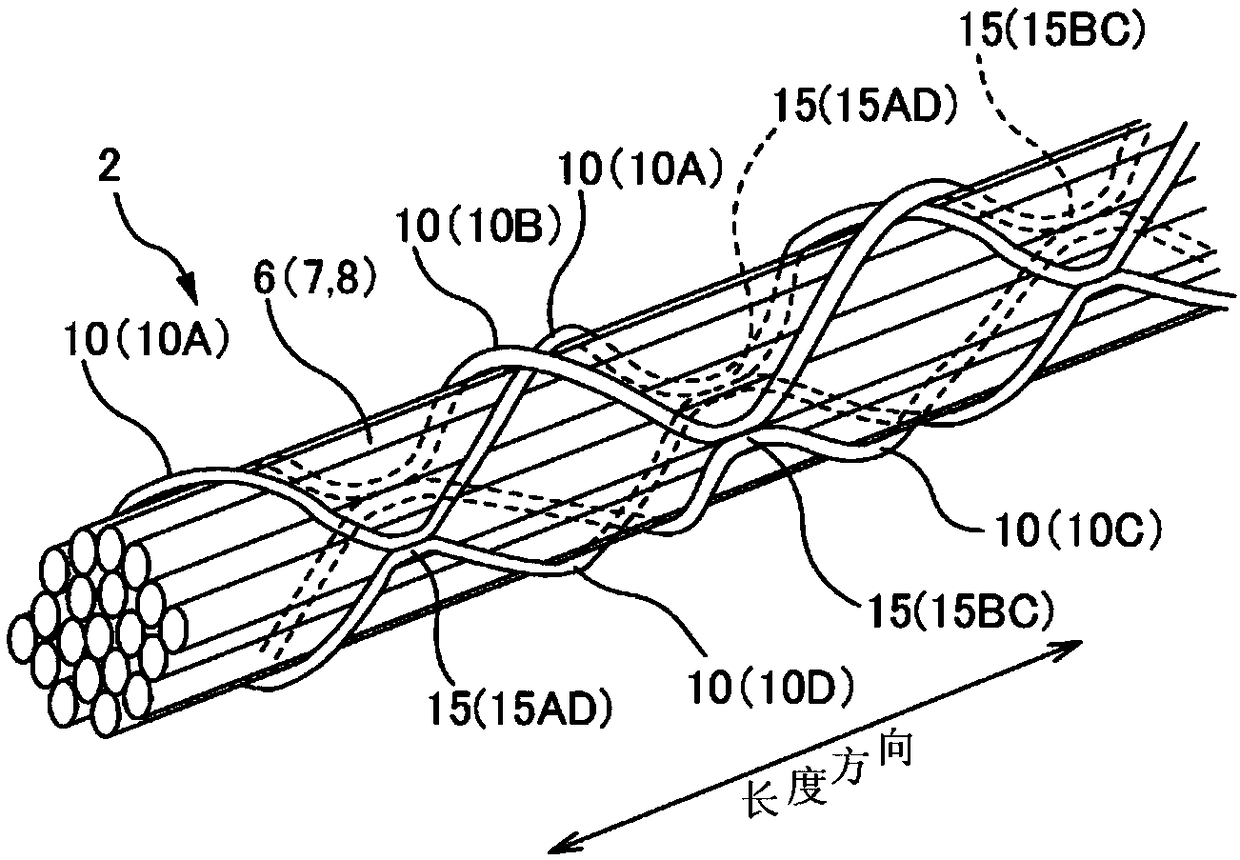
[0053] The entanglement of the optical fiber at the junction of the binders 10 is caused by the erection of the junction of the binders when the width W to the thickness T of the binder is equal to or greater than a certain value. Therefore, a plurality of trial-manufactured optical fiber units were manufactured with respect to the cross-sectional dimensions of the binder, and the evaluation of the entanglement characteristics at the junction between the binders 10 was performed.
[0054] First, a plurality of trial-manufactured optical fiber units assembled 80 optical fiber core wires and wound the bundle into an SZ shape. The winding method of the bundle and Figure 1B and Figure 5 Same as shown. A plurality of trial optical fiber units were manufactured with different widths and thicknesses, and when they were rotated and brought into contact with other optical fiber units, it was evaluated wh...
no. 2 approach
[0062]
[0063] In the above reference example, when the optical fiber unit is bent, the optical fiber core wires protrude from the gap enclosed by the binding members. The protruding portion of the optical fiber core is caught in other optical fiber units or bundles, and is locally bent, resulting in an increase in transmission loss and breakage of the optical fiber core.
[0064] Figure 8 It is a figure for explaining the optical fiber unit 2 in which the optical fiber core wire 8 protrudes. in addition, Figure 8 For ease of description, only one of the binding members 10 is shown in the figure, and the other binding members 10 joined thereto are not shown. In the following description, a suffix (A, B) will be added to the optical fiber core wire 8 for description. like Figure 8 As shown, when a bend is applied to the optical fiber unit 2 , a difference in line length occurs between the trajectories of the optical fiber core wire 8 from the point S to the point E. ...
PUM
| Property | Measurement | Unit |
|---|---|---|
| Length | aaaaa | aaaaa |
Abstract
Description
Claims
Application Information
 - R&D Engineer
- R&D Manager
- IP Professional
- Industry Leading Data Capabilities
- Powerful AI technology
- Patent DNA Extraction
Browse by: Latest US Patents, China's latest patents, Technical Efficacy Thesaurus, Application Domain, Technology Topic, Popular Technical Reports.
© 2024 PatSnap. All rights reserved.Legal|Privacy policy|Modern Slavery Act Transparency Statement|Sitemap|About US| Contact US: help@patsnap.com