
Regenerative peritoneal dialysis system

A technology of peritoneal dialysis fluid and control system, applied in the field of devices for producing peritoneal dialysis fluid

Inactive Publication Date: 2018-11-23
MEDTRONIC INC
View PDF5 Cites 1 Cited by
  • Summary
  • Abstract
  • Description
  • Claims
  • Application Information

AI Technical Summary

Problems solved by technology

Thus, the known treatments require considerable quantities of clean water, which can prevent the use of the known systems, especially in areas where clean water is scarce

Method used


Image

  • Regenerative peritoneal dialysis system
  • Regenerative peritoneal dialysis system
  • Regenerative peritoneal dialysis system

Examples


Embodiment Construction

[0062] Unless otherwise defined, all technical and scientific terms used have the same meaning as commonly understood by one of ordinary skill in the art.

[0063] The articles "a / an" are used to refer to one or more than one (ie, at least one) of the grammatical objects of the item. For example, "an element" means one element or more than one element.

[0064] "Activated carbon" refers to a form of carbon that has been processed to have small pores, increasing the surface area available for adsorption.

[0065] As used herein, the term "amino acid" refers to any nitrogen-containing organic acid or peptide that can be used as an osmotic agent to produce peritoneal dialysis fluid.

[0066] The term "source of calcium chloride" refers to a source of calcium chloride in solid and / or solution form. The calcium chloride source may contain at least one fluid channel and include components such as conduits, valves, filters or fluid connection ports, any of which may be fluidly conn...


PUM


Abstract

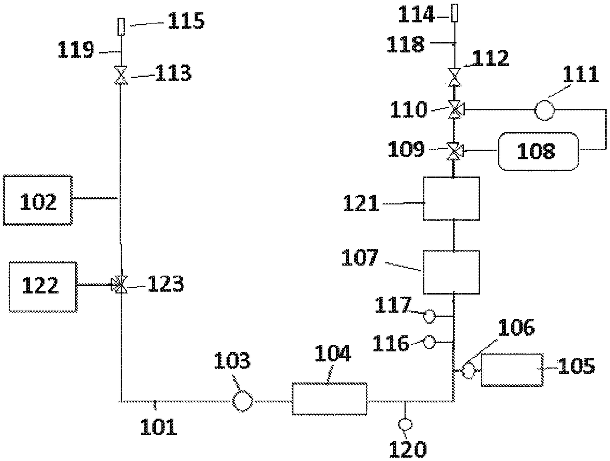
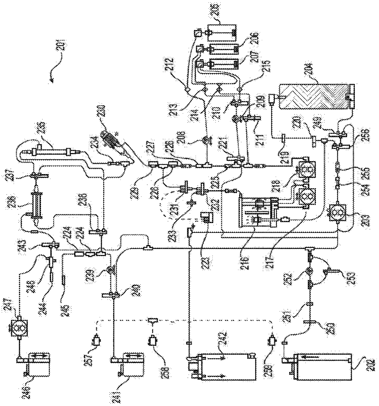
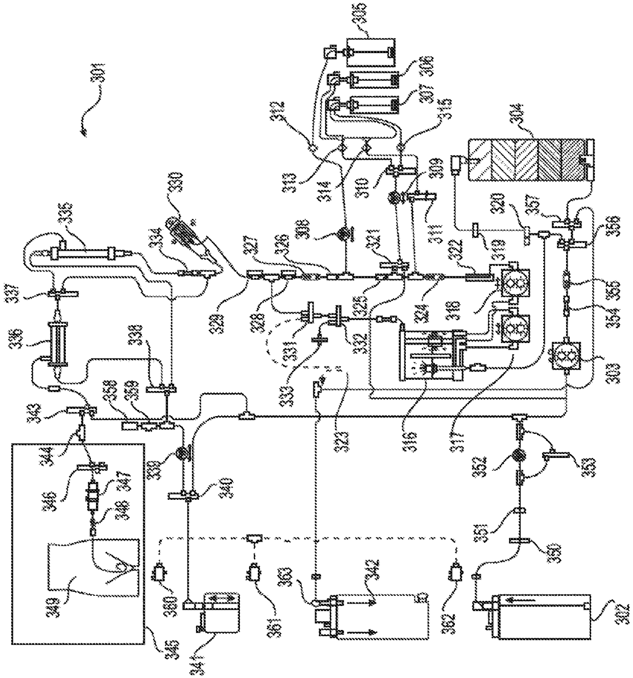
Systems and methods of generating and regenerating peritoneal dialysate are provided. The systems and methods use a dialysate regeneration module (104), a sterilization module (107, 121), and concentrates (105) to prepare peritoneal dialysate from used peritoneal dialysate or source water (102). An optional integrated cycler for direct infusion of the generated peritoneal dialysate is included. Optional dialysate storage containers are provided for storage of the peritoneal dialysate prior to use.

Description

technical field [0001] The present invention relates to devices, systems and methods for producing peritoneal dialysis fluid having a purity and sterility properties suitable for peritoneal dialysis (PD) and regenerating spent fluid for subsequent use. The peritoneal dialysis fluid can be generated or regenerated from water or spent variable mass fluid using the dialysate generating flow path containing the sterilizing module. The sterilization module can be any one or more of an ultrafilter, an ultraviolet (UV) light source, a microbial filter, a dialyzer, and combinations thereof. The peritoneal dialysis fluid generation system and related methods can automatically generate peritoneal dialysis fluid using an integrated circulator and provide peritoneal dialysis treatment to a patient and regenerate spent fluid for subsequent use as fresh peritoneal dialysis fluid. Background technique [0002] Peritoneal dialysis (PD), including Automated Peritoneal Dialysis (APD) and Con...

Claims


Application Information

Patent Timeline
Patent Type & Authority Applications(China)
IPC IPC(8): A61M1/16A61M1/28C02F1/00C02F1/02C02F1/28C02F1/32C02F1/44
CPCA61M1/1656A61M1/1686A61M1/1696A61M1/28A61M2205/7518A61M1/1666A61M1/1672A61M1/1674C02F1/283C02F1/325C02F1/42C02F1/441C02F1/442C02F1/444C02F2303/04A61K33/00A61K31/7004A61K31/715A61K31/198A61M2205/75A61M2205/502A61M1/159A61M1/282A61M1/287A61L2/0047A61L2/0017A61M2209/10A61M2205/36A61M2205/3337A61M2205/50A61L2202/21
Inventor 文卡特斯·R·曼达马丁·T·格伯克里斯多夫·M·霍博特大卫·B·卢拉托马斯·E·迈耶
Owner MEDTRONIC INC
Learn More