High power microspeaker with sub-diaphragm

A micro-speaker, high-power technology, applied in the direction of planar diaphragm, loudspeaker, sensor, etc., can solve the problems of uneven air intake, diaphragm deformation, increase the stiffness of the acoustic system, etc., to improve the vibration balance and suppress the diaphragm Effect of deformation and improvement of THD characteristics

Inactive Publication Date: 2018-11-23
EM TECHNOLOGY CO LTD
View PDF6 Cites 1 Cited by
  • Summary
  • Abstract
  • Description
  • Claims
  • Application Information

AI Technical Summary

Problems solved by technology

This air pocket generates heat in the diaphragm, which is not good for high power speakers, and this air pocket increases the stiffness of the entire acoustic system, which leads to a drop in sound pressure level (SPL)
In addition, the air intake between the upper edge part and the lower edge part is not smooth, which causes the diaphragm to deform during vibration

Method used


Image

  • High power microspeaker with sub-diaphragm
  • High power microspeaker with sub-diaphragm
  • High power microspeaker with sub-diaphragm

Examples


Embodiment Construction

[0044] Hereinafter, preferred embodiments of a high-power microspeaker with a sub-diaphragm according to the present invention will be described in detail with reference to the accompanying drawings.

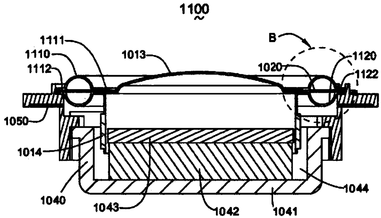
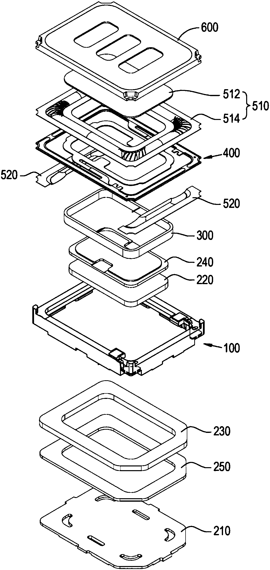
[0045] The present invention provides a structure in which an acoustic system of a microspeaker including a main diaphragm and a conductive suspension is attached to the top surface of a coil, and a separate sub-diaphragm is attached to the same surface of the coil.

[0046] Furthermore, the present invention provides a structure in which one main diaphragm and one conductive suspension are coupled to each other, and two or more sub-diaphragms are attached to a lower portion of the conductive suspension.

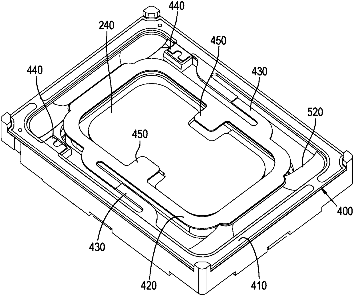
[0047] The present invention also provides a structure in which the microspeaker is formed in a rectangular shape, and the sub-diaphragm is attached to the short side of the acoustic system and extends to the corner.

[0048] Furthermore, the present invention provides a struc...


PUM


Abstract

The present invention relates to a high power microspeaker having a separate sub-diaphragm on a top end surface of a coil, in addition to a diaphragm and a suspension. The present invention provides astructure in which an acoustic system including a main diaphragm and a conductive suspension of a microspeaker is attached to a top end surface of a coil and a separate sub-diaphragm is attached to the same surface of the coil.

Description

technical field [0001] The present invention relates to a high-power microspeaker having a separate sub-diaphragm on the top surface of a coil in addition to a diaphragm and a suspension. Background technique [0002] Generally, a microspeaker includes a magnetic circuit, a coil that vibrates due to electromagnetic force interacting with the magnetic circuit, and a diaphragm that is attached to the diaphragm that vibrates and emits sound as the coil vibrates. [0003] In the vibration of the coil, the diaphragm does not always vibrate in the desired direction—that is, the direction perpendicular to the diaphragm—but biased vibration or split vibration occurs, which distorted sound. Therefore, a suspension or the like is further provided between the diaphragm and the coil to solve the above-mentioned problems. [0004] However, since high power is required for a microspeaker, factors causing bias vibration or split vibration increase, such as an increase in the overall heig...

Claims


Application Information

Patent Timeline
Patent Type & Authority Applications(China)
IPC IPC(8): H04R9/06H04R9/02
CPCH04R9/025H04R9/06H04R2400/11H04R7/04H04R9/045H04R7/127
Inventor 金千明金志勋郑性哲南瑟基
Owner EM TECHNOLOGY CO LTD
Why Eureka
Try Eureka