
Power distribution system, capacity sharing system, master station, sub-station, method and equipment

A technology of power distribution equipment and main station, which is applied in the field of charging and swapping, and can solve problems such as power grid rated power limitation, frequent power outage accidents, and affecting users' daily life and normal travel.

Active Publication Date: 2018-11-23
NIO ANHUI HLDG CO LTD
View PDF5 Cites 12 Cited by
  • Summary
  • Abstract
  • Description
  • Claims
  • Application Information

AI Technical Summary

Problems solved by technology

If it is necessary to build charging facilities in a centralized and large area, it is difficult to find a place that can provide corresponding power supply capacity
Even if the charging facilities are put into use, they will be limited by the rated power of the grid
This problem is particularly prominent in the existing parking lot and the charging pile expansion project of the old community: the power consumption capacity of the existing parking lot or the old community is usually planned, and the capacity cannot be increased under normal circumstances. If a large number of charging facilities are added due to the increase in capacity, it is likely to cause an impact on the power grid due to the simultaneous use of multiple charging facilities, resulting in large-scale power outages, which not only affect the daily life and normal travel of users, but also cause power outages. Frequent hair loss is also not conducive to the use of electric vehicles

Method used


Image

  • Power distribution system, capacity sharing system, master station, sub-station, method and equipment
  • Power distribution system, capacity sharing system, master station, sub-station, method and equipment
  • Power distribution system, capacity sharing system, master station, sub-station, method and equipment

Examples


Embodiment Construction

[0374] Preferred embodiments of the present invention are described below with reference to the accompanying drawings. Those skilled in the art should understand that these embodiments are only used to explain the technical principle of the present invention, and are not intended to limit the protection scope of the present invention.

[0375] It should be noted that, in the description of the present invention, the terms "first" and "second" are only for the convenience of description, rather than indicating or implying the relative importance of the devices, elements or parameters, so they should not be understood as important to the present invention. Invention Limitations.

[0376]On the time and space scales, the charging demand has space-time imbalance. The charging demand is initiated by the user on the charging facility, and is reflected in the overall load demand on the power grid through the power transmission and distribution system to the power supply side. The c...


PUM


Abstract

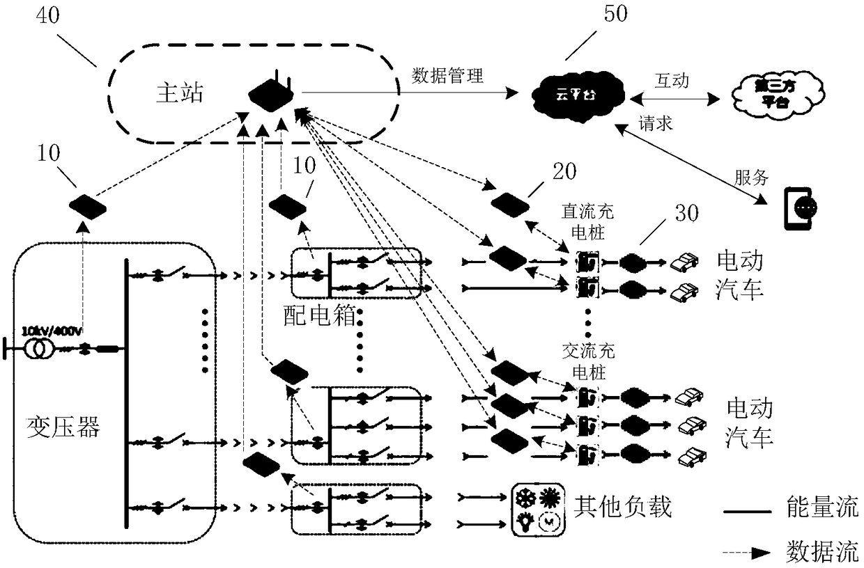
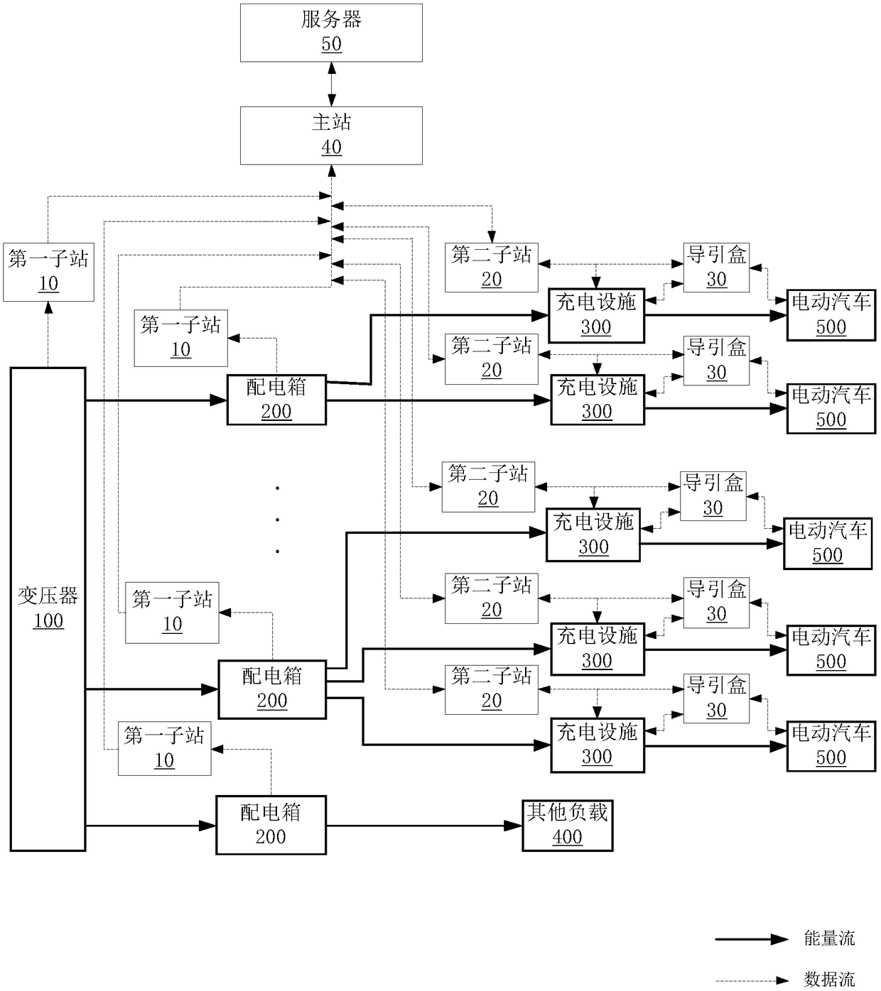
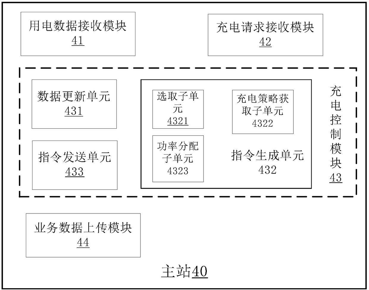
The invention relates to the technical field of charging and power conversion, in particular to a power distribution system, a capacity sharing system, a master station, a sub-station, a method and equipment and aims to solve the problem how a charging facility is additionally arranged on the basis of capacity of a traditional power grid and achieve power optimization and utilization of the powergrid. The capacity sharing system comprises a terminal group, the master station and a server, wherein the terminal group comprises a first sub-station, a second sub-station and a guidance box, the master station is used for receiving power utilization data acquired by the first sub-station and a charging request acquired by the second sub-station in the corresponding terminal group ad calculatingand sending a charging instruction to the corresponding sub-station, the second sub-station is used for receiving the charging instruction of the master station and generating and issuing a control instruction to the guidance box, the guidance box is used for charging an output power of the charging facility according to the control instruction, the master station is further used for uploading charging service data to the server, and the server is used for judging a running state of a power distribution system according to the charging service data. By the capacity sharing system, electric energy sharing and ordered charging in a special region are achieved, and moreover, the system is more stable to run.

Description

technical field [0001] The invention relates to the technical field of charging and swapping, and in particular to a power distribution system, a capacity sharing system, a master station, a substation, a method and a device. Background technique [0002] With the popularity of new energy vehicles, how to effectively supply energy for new energy vehicles with insufficient energy has become the focus of attention of car owners and major manufacturers. Among them, the construction of charging facilities (such as the construction of charging piles that can provide charging power for electric vehicle batteries) is one of the mainstream solutions to solve the above problems. Taking charging piles for electric vehicles as an example, charging piles are widely installed in parking lots, residential quarters, large shopping malls, and service areas due to their small footprint, low cost, and ease of use. When using the charging pile, the user only needs to pull out the charging gun...

Claims


Application Information

Patent Timeline
Patent Type & Authority Applications(China)
IPC IPC(8): H02J7/00
CPCH02J7/0026
Inventor 戴晨松刘隽吴广涛陈炯
Owner NIO ANHUI HLDG CO LTD
Learn More