
A multi-voltage level DC power grid system and its control and protection method

A multi-voltage level, DC power grid technology, applied in DC network circuit devices, emergency protection circuit devices for limiting overcurrent/overvoltage, emergency protection circuit devices, etc., can solve the problem of small DC system line impedance, DC bus voltage Pull down, affect equipment load and other problems, to achieve the effect of reducing the rate of change of fault current, improving the success rate and low cost

Active Publication Date: 2020-06-05
NR ELECTRIC CO LTD +1
View PDF6 Cites 0 Cited by
  • Summary
  • Abstract
  • Description
  • Claims
  • Application Information

AI Technical Summary

Problems solved by technology

[0002] In recent years, the application range of DC grid technology has become more and more extensive. Due to the introduction of a large number of power electronic converters, the operation mode of DC grid is more flexible and more complex. How to effectively ensure the reliability of DC grid operation has become a limiting DC power grid. The bottleneck of network development: due to the small line impedance of the DC system, once a short-circuit fault occurs, on the one hand, the short-circuit current rises very fast, and the power electronic converter is composed of power semiconductors, and the overcurrent capability of power semiconductor devices is limited. The current will cause damage or blockage of the converter; on the other hand, the short-circuit current caused by the short circuit of the outgoing line will pull down the DC bus voltage, and the reduction of the DC bus voltage will affect all equipment and loads connected to the same bus.

Method used


Image

  • A multi-voltage level DC power grid system and its control and protection method
  • A multi-voltage level DC power grid system and its control and protection method
  • A multi-voltage level DC power grid system and its control and protection method

Examples


Embodiment Construction

[0051] The technical solution of the present invention will be described in detail below in conjunction with the accompanying drawings.

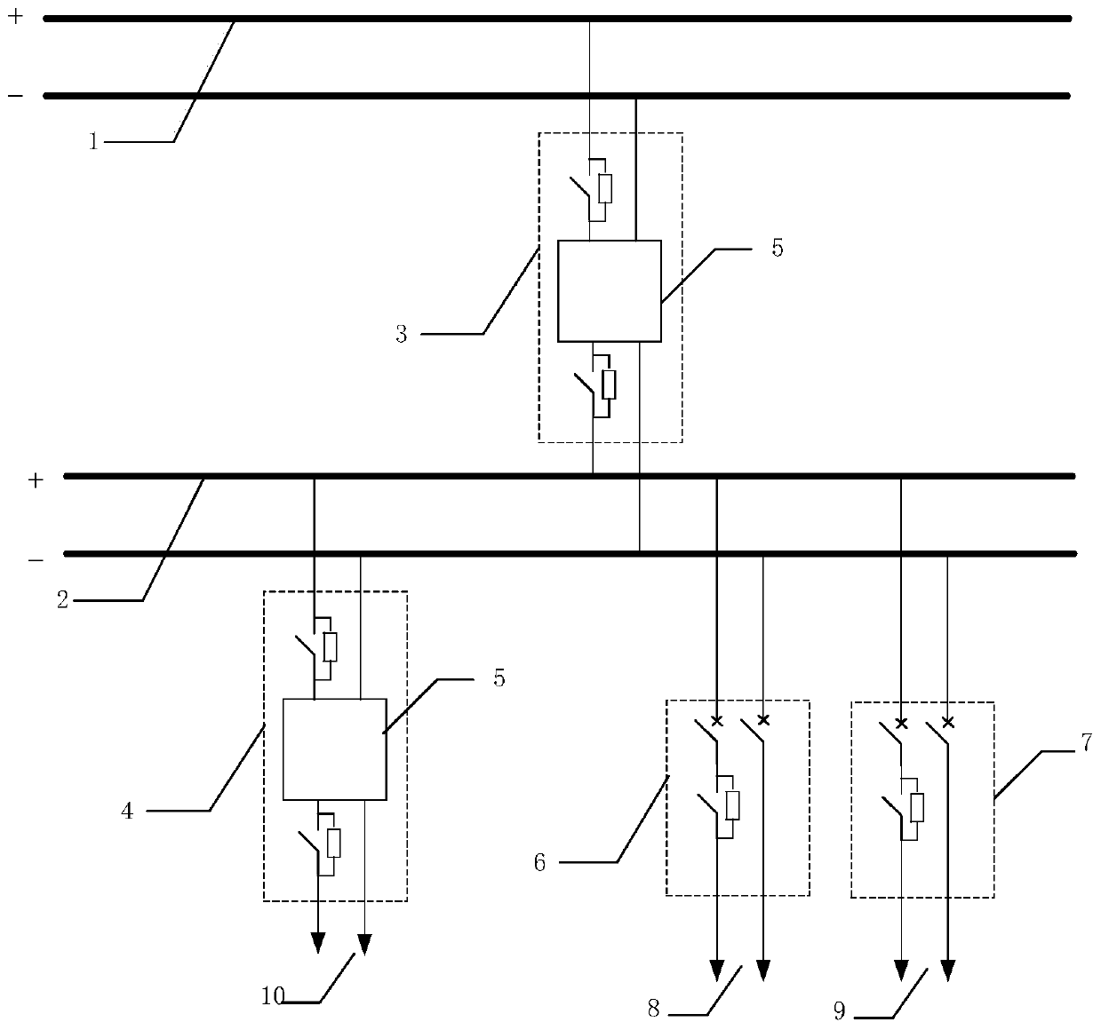
[0052] A multi-voltage level DC power grid system, wherein the DC power grid system has at least one DC transformer, at least two DC buses, and at least one outlet current limiter;

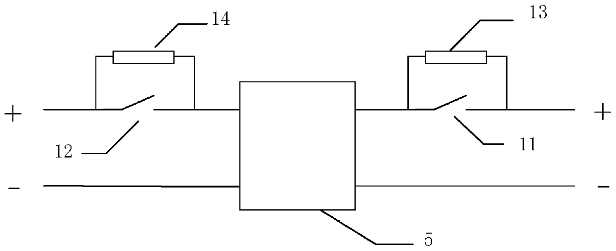
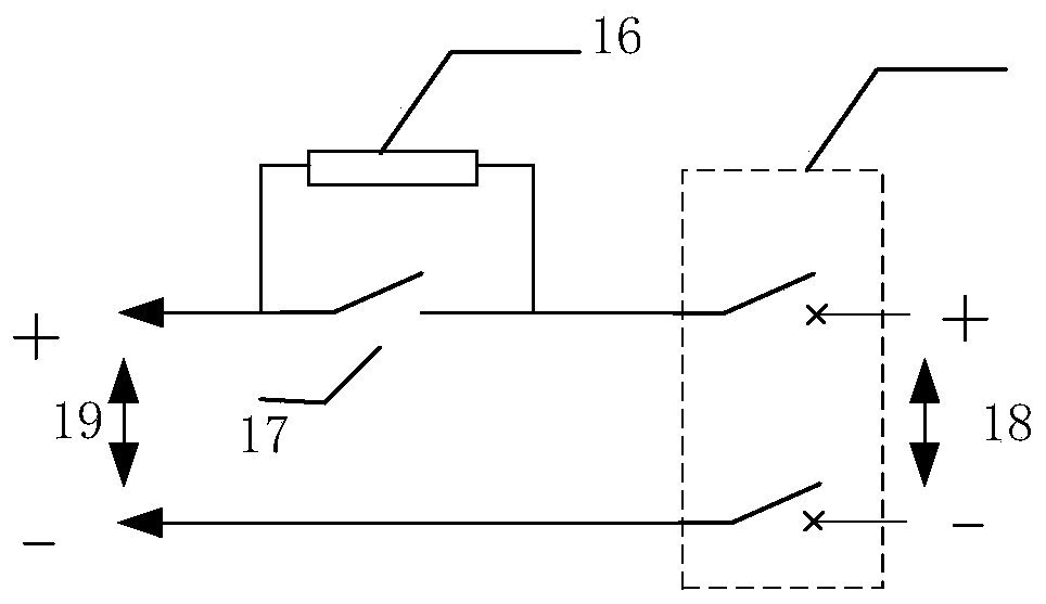
[0053] One end of the DC transformer is connected to the first DC bus, and the other end is connected to the second DC bus to realize DC voltage conversion; the outlet current limiter includes a set of DC switches and a first bypass switch and a first limiter. The first current limiting unit constituted by the current resistance unit in parallel, one end of the outlet current limiter is connected with the DC bus, and the other end is connected with the outlet.

[0054] Such as figure 1 As shown, in this embodiment, the DC power grid system includes two DC transformers, two DC buses, two outgoing current limiters, and three outgoing lines. The DC transformer 1 is conne...


PUM


Abstract

The invention discloses a multi-voltage level direct current power grid system. The direct current power grid system has at least one direct current transformer, at least two direct current busbars and at least one outlet current limiter; one end of the direct current transformer is connected to the first direct current busbar, and the other end It is connected with the second DC bus to realize DC voltage conversion; the outlet current limiter includes a group of DC switches and a first current limiting unit composed of a first bypass switch and a first current limiting resistor unit connected in parallel. The present invention also includes a control and protection method for a DC power grid system with multiple voltage levels. When a short-circuit fault occurs in the DC power grid busbar or outgoing line, the short-circuit current can be reduced by quickly investing in a current-limiting resistor unit, and the busbar voltage can be kept normal to realize the failure. Ride-through greatly improves the operational reliability of the DC power grid.

Description

Technical field [0001] The invention belongs to the field of power electronic converters, and particularly relates to a multi-voltage-level DC power grid system and a control and protection method. Background technique [0002] In recent years, the application of DC grid technology has become more and more extensive. Due to the introduction of a large number of power electronic converters, the operation of the DC grid is more flexible and more complicated. How to effectively ensure the reliability of the DC grid operation has become a limitation of DC power The bottleneck of network development: due to the small line impedance of the DC system, once a short-circuit fault occurs, on the one hand, the short-circuit current rises very quickly, and the power electronic converter is composed of power semiconductors, and the overcurrent capability of power semiconductor devices is limited, and short-circuit Current will cause the converter to be damaged or blocked; on the other hand, t...

Claims


Application Information

Patent Timeline
Patent Type & Authority Patents(China)
IPC IPC(8): H02H7/26H02H9/02
CPCH02H7/268H02H9/02H02J1/082H02J1/00H02H7/26H02H1/0007
Inventor 谢晔源李海英王宇张中锋曹冬明
Owner NR ELECTRIC CO LTD
Learn More