
Design method for optimal controller of linear discrete time system with control time delay

A linear discrete time system technology, applied in design optimization/simulation, instrumentation, calculation, etc., can solve problems such as the unresolved exponential stability of linear discrete time systems

Active Publication Date: 2018-11-23
SUZHOU UNIV OF SCI & TECH
View PDF5 Cites 2 Cited by
  • Summary
  • Abstract
  • Description
  • Claims
  • Application Information

AI Technical Summary

Problems solved by technology

So far, the problem of exponential stability of linear discrete-time systems with controlled delays remains unsolved

Method used


Image

  • Design method for optimal controller of linear discrete time system with control time delay
  • Design method for optimal controller of linear discrete time system with control time delay
  • Design method for optimal controller of linear discrete time system with control time delay

Examples


Embodiment 1

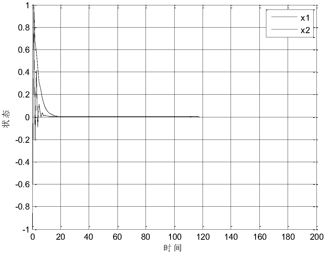
[0123] The linear discrete time system with control delay is as follows,

[0124] x k+1 =Ax k +Bu k +B 1 u k-3

[0125] among them

[0126]

[0127] The parameters selected in the simulation are as follows:

[0128] F=diag(1,1), Q=diag(0.01,0.01),

[0129] R=1, N=200

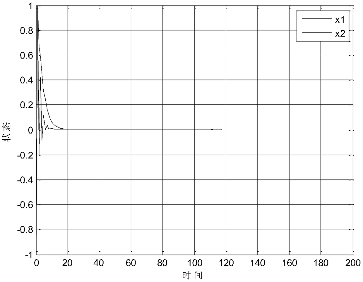
[0130] For the finite time optimal control of the system, calculate P in equation (4) k The value of is not very convenient, P k Calculation method and literature (HLLiu, QXZhu, New Forms of Riccati equations and the further results of the optimal control for linear discrete-time systems. International Journalof Control, Automation and Systems. 2014, 12(6): 1160-1164. The calculation method in) is the same. When P N ,P N-1 ,LP 2 ,P 1 When the value of is known, the finite time optimal controller of the system can be calculated. When the initial value of the system is x 0 =[1-1] T When the state of the closed-loop system responds as figure 1 Shown. From figure 1 It can be seen that the closed-loop system with a finite...

Embodiment 2

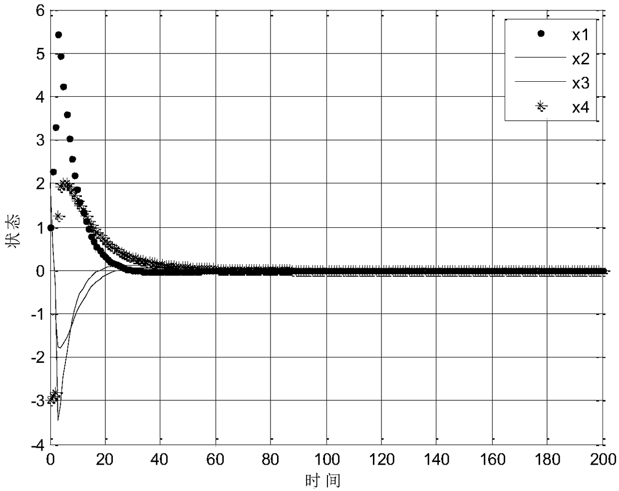
[0134] The linear discrete time system with control delay is as follows,

[0135] x k+1 =Ax k +Bu k +B 1 u k-2

[0136] among them

[0137]

[0138]

[0139] The parameters selected in the simulation are as follows:

[0140] F=diag(1,1,1,1), Q=diag(0.1,0.1,0.1,0.1),

[0141] R=diag(1,1), N=200

[0142] For the finite time optimal control of the system, P k The calculation method of is the same as in the first embodiment. The initial value in the system is x 0 =[1 1 -2 -3] T When the state of the closed-loop system responds as image 3 Shown. From image 3 It can be seen that the closed-loop system with a finite-time optimal conversion controller is exponentially stable. For the infinite time optimal control of the system, it is easy to know that the system is controllable. Use Matlab function DARE to get the value of P as follows.

[0143]

[0144] The initial value in the system is x 0 =[1 -1 2 -3] T When, the state response of the closed-loop system with the infinite time optimal co...


PUM


Abstract

The invention discloses a design method for an optimal controller of a linear discrete time system with control time delay. The method converts the linear discrete time system with control time delayinto an equivalent linear discrete time system with no control time delay through a multi-step transformation of a memorized memory; then obtains a controller of the linear discrete time system with control time delay by designing a finite time optimal controller of the equivalent linear discrete time system without control time delay; and obtains the controller of the linear discrete time systemwith control time delay by designing an infinite time optimal controller of the equivalent linear discrete time system without control time delay. According to the design method for optimal controllerof linear discrete time system with control time delay, an optimal control for multi-step transformation of a linear discrete time system with control time delay is provided on the basis of memoryless transformation, , and the dimension of the system will not increase and the obtained optimal controller can stabilize a closed-loop system index when using such transformation.

Description

Technical field [0001] The present invention relates to the field of controller design, in particular to an optimal controller design method for a linear discrete time system with control time delay. Background technique [0002] Time delay is often the main source of system instability, and it appears in various engineering systems, such as long transmission lines in chemical processes and pneumatic systems. The stability standards of time delay systems have attracted the attention of many researchers. They can be divided into two categories: delay-dependent standards and delay-independent standards. The latter does not include any information about the size of the delay, while the former includes this information. So far, the problem of exponential stability of linear discrete-time systems with control delays has not been solved. Summary of the invention [0003] The present invention provides an optimal controller design method for a linear discrete time system with control ti...

Claims


Application Information

Patent Timeline
IPC IPC(8): G06F17/50
CPCG06F30/20Y02P90/02
Inventor 朱其新
Owner SUZHOU UNIV OF SCI & TECH
Learn More