
A gun sight video interface device

A video interface and equipment technology, applied in offensive equipment, digital video signal modification, TV, etc., can solve the problems of easily exposing one's own vital parts and insufficient control of the front battlefield situation, so as to improve survivability and combat ability, and improve survivability , the effect of saving energy

Active Publication Date: 2020-04-17
THE 28TH RES INST OF CHINA ELECTRONICS TECH GROUP CORP
View PDF5 Cites 0 Cited by
  • Summary
  • Abstract
  • Description
  • Claims
  • Application Information

AI Technical Summary

Problems solved by technology

[0004] The technical problem to be solved by the present invention: the purpose of the present invention is to solve the deficiencies in the prior art. It provides a gun aiming video interface device, which can provide soldiers with the ability to shoot at head-up and at corners, and solve the problem of soldiers using the existing When aiming at the equipment, you must observe the aiming device, and it is easy to expose your vital parts in close-range firefights
At the same time, the broadband network communication equipment can enable the rear command organization to grasp the gun sight observation images of multiple soldiers in real time, effectively solving the problem of insufficient control of the front battlefield situation by the rear command organization without adding additional equipment or increasing the burden on soldiers.

Method used

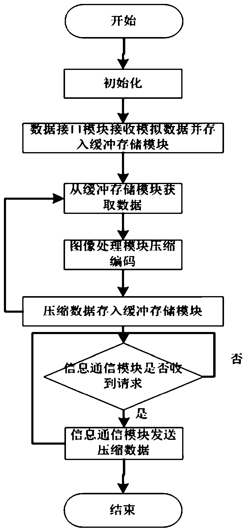

Image

  • A gun sight video interface device
  • A gun sight video interface device
  • A gun sight video interface device

Examples


Embodiment Construction

[0040] The present invention will be further described below in conjunction with the accompanying drawings and embodiments.

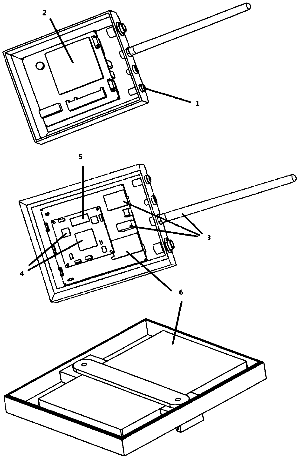
[0041] figure 1 A schematic diagram of each module inside the gun sight video interface device is given. As shown in the figure, a gun sight video interface device, the gun sight video interface device includes a data interface module 1, a centralized control module 2, an information communication module 3, an image processing module 4, a buffer storage module 5, and a power supply module 6 .

[0042]The data interface module 1 is connected with the video output interface of the digital sight, the centralized control module 2, and the power supply module 6, and is used for connecting the gun sight image data of the digital sight to an external target; the centralized control module 2 and the The data interface module 1, the information communication module 3, the image processing module 4, the buffer storage module 5, and the power supply module 6 are...


PUM


Abstract

The invention discloses video interface equipment for gun aiming. The video interface equipment for gun aiming comprises a data interface module, a concentrated control module, an information communication module, an image processing module, a buffer storage module and a power supply module. A digital gun aiming system is composed of the equipment, a digital aiming tool, intelligent head-mounted display equipment and broadband wireless network communication equipment. The system is capable of providing the capacities of head-up shooting, corner shooting and the like for soldiers, thereby solving the problem that an aiming device needs to be observed when the soldiers use existing aiming equipment, and the own critical parts are easily exposed in close-range fight. Meanwhile, a rear commanding mechanism is enabled to acquire the gun aiming observation windows of the plurality of soldiers in real time through the broadband wireless network communication equipment, so that the problem ofinsufficient control of the rear commanding mechanism on the condition of a front battlefield is effectively solved in the case of not additionally adding equipment and increasing the burden of the soldiers.

Description

technical field [0001] The present invention relates to a gun sight video interface device, in particular to a gun sight video interface device which forms a digital gun sight system together with a digital sight, an intelligent head-mounted display device and a broadband wireless network communication device. Background technique [0002] In informationized and intelligent modern warfare, except for a small number of special combatants, ordinary soldiers still mainly use the three-point-one-line method for aiming and shooting. This aiming method not only has low hit accuracy, but also takes a long time from raising the gun to aiming to completing the aiming process. For some soldiers who use sights for aiming, although the weapon's hit accuracy is improved, the sights will limit their own binocular field of vision, affecting soldiers' observation and judgment of situations other than the target. In addition, in complex combat situations such as close-range firefights, stre...

Claims


Application Information

Patent Timeline
Patent Type & Authority Patents(China)
IPC IPC(8): F41G1/00H04N5/765H04N5/268H04N19/42H04W76/10
CPCF41G1/00H04N5/268H04N5/765H04N19/42H04W76/10
Inventor 周远远吕路张崟王方顺刘石李飞翔杨波刘超周展张红
Owner THE 28TH RES INST OF CHINA ELECTRONICS TECH GROUP CORP
Learn More