Exhaust hood with smoke collecting cavity capable of ascending and descending

A range hood and smoke collecting cavity technology, which is applied in the field of kitchen appliances, can solve problems such as difficult maintenance, stuck smoke collecting cavity, shaking, etc., and achieve the effect of optimizing the guiding structure, not hindering the line of sight, and adjusting the height

Pending Publication Date: 2018-11-23
浙江友邦智能厨电有限公司
View PDF6 Cites 3 Cited by
  • Summary
  • Abstract
  • Description
  • Claims
  • Application Information

AI Technical Summary

Problems solved by technology

[0004] However, the existing side-suction range hoods with a liftable smoke-collecting chamber also have the following defects: 1. The smoke-collecting chamber is built into the casing for lifting, which easily leads to the accumulation of oil on the outer surface of the smoke-collecting chamber, and the accumulated oil in the casing Oil is easy to leak from between the smoke collecting chamber and the housing; 2. The smoke collecting chamber is built into the housing for lifting, and the guide structure such as guide rails is easy to deposit dirt, which will cause the smoke collecting chamber to be stuck, unable to work normally, and difficult to maintain; 3. The guide structure is not reasonable enough, the lifting stability of the smoke collection chamber is poor, there are problems such as shaking and loud lifting noise
Due to the existence of the above defects, the side suction range hood with a liftable smoke collection chamber has not been commercially applied.

Method used


Image

  • Exhaust hood with smoke collecting cavity capable of ascending and descending
  • Exhaust hood with smoke collecting cavity capable of ascending and descending
  • Exhaust hood with smoke collecting cavity capable of ascending and descending

Examples


Embodiment 1

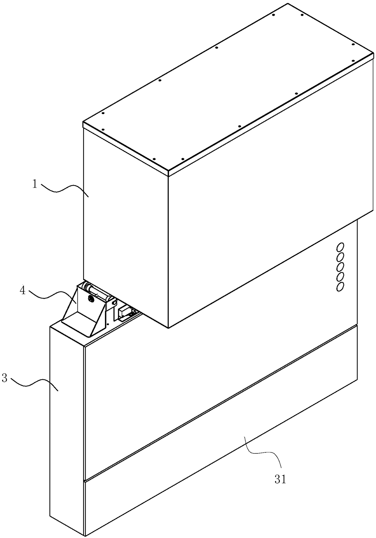
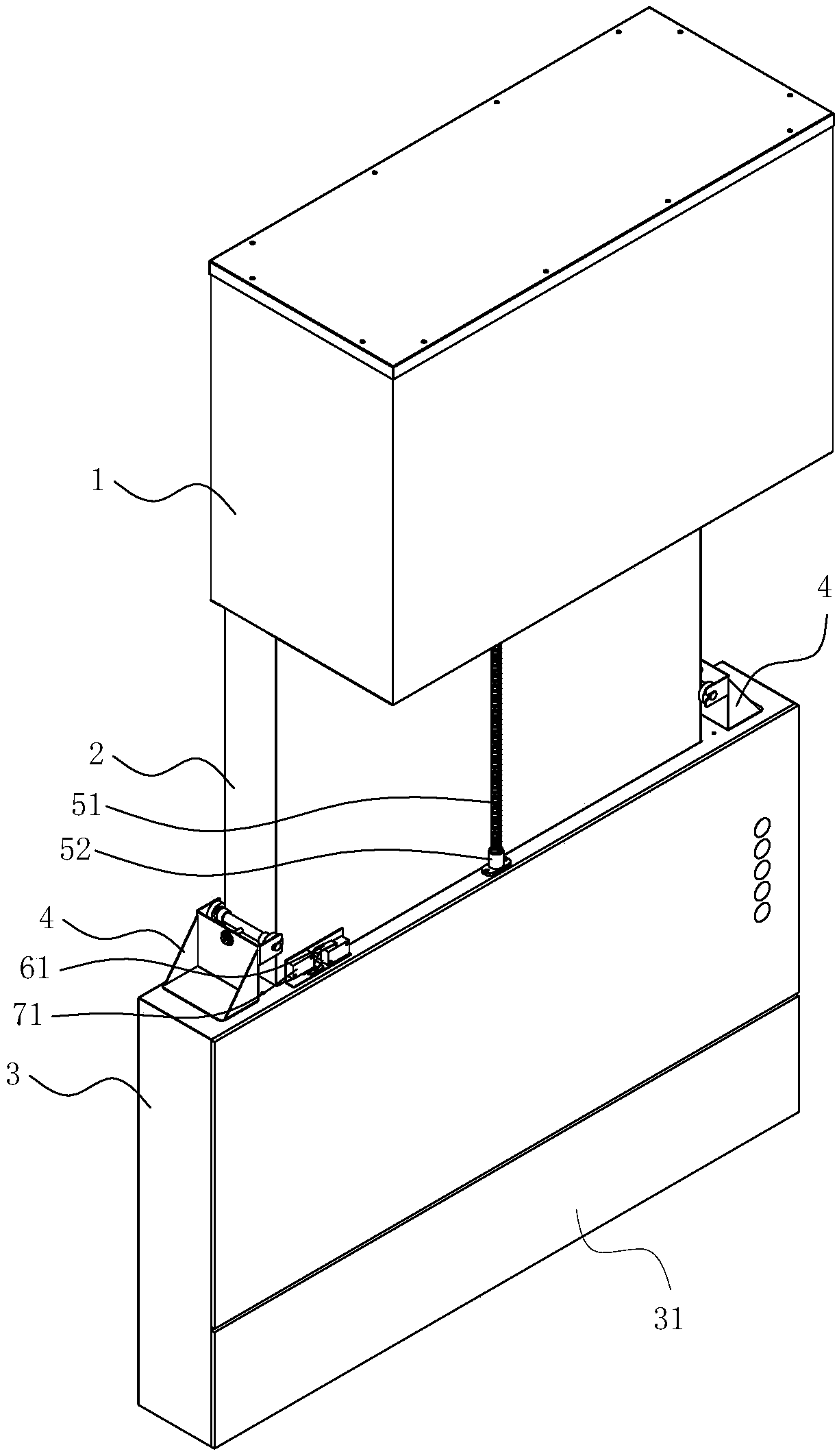
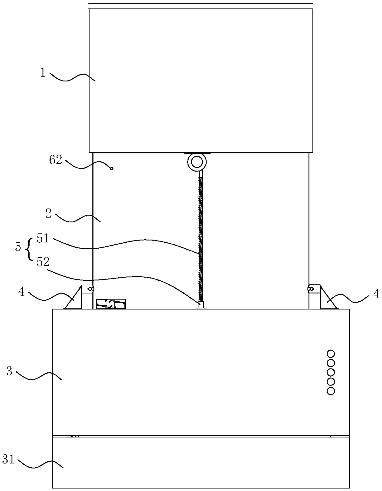
[0058] see Figure 1 to Figure 9 , a range hood with a liftable smoke collecting cavity, comprising: a smoke box 1 having an air inlet and an air exhaust port;

[0059] The fan F is installed in the smoke box 1, the air inlet of the fan F communicates with the air inlet of the smoke box 1, and the air outlet of the fan F communicates with the air outlet of the smoke box 1;

[0060] The flue 2 is arranged under the smoke box 1, the flue 2 has an air inlet and an air outlet, and the air outlet of the flue 2 communicates with the air inlet of the smoke box 1;

[0061] The smoke collecting chamber 3 is arranged outside the flue 2 in a liftable manner, and the smoke collecting chamber 3 has a damper 31, and the damper 31 is located on the front side of the smoke collecting chamber 3;

[0062] The lifting mechanism drives the smoke collecting chamber 3 to move up and down relative to the flue 2;

[0063] A guiding mechanism, used to make the smoke collecting chamber 3 rise and fal...

Embodiment 2

[0085] The difference between the second embodiment and the first embodiment mainly lies in the guide pulley assembly 4 .

[0086] see Figure 10 and Figure 11 In this embodiment, the guide pulley assembly 4 is arranged outside the smoke collection chamber 3, compared with the first embodiment in which part of the guide pulley assembly 4 is arranged inside the smoke collection chamber 3, the accumulation of oil on the guide pulley assembly 4 can be reduced.

[0087] Pulley 43 frame 41 is provided with upper and lower two groups of parallel pulley shafts 42, pulley 43, adjusting screw rod 44, adjusting nut 45, flat washer 47 and jump ring 46.

[0088] The air outlet of the smoke box 1 is arranged on the side plate, and the top plate of the smoke box 1 is also provided with a deodorizing air inlet hole, which is connected to the deodorizing air inlet through a pipe, and the deodorizing air inlet is vertically air-inlet, and the deodorizing air inlet The tuyere can be set abov...


PUM


Abstract

The invention belongs to the technical field of a kitchen electric appliance, and particularly relates to an exhaust hood with a smoke collecting cavity capable of ascending and descending. By aimingat the defects of the existing lateral suction type exhaust hood with the smoke collecting cavity capable of ascending and descending that the smoke collecting cavity is built in a casing, so that oilstain can be easily leaked out from a position between the casing and the smoke collecting cavity, the exhaust hood provided by the invention has the following technical scheme that the exhaust hoodwith the smoke collecting cavity capable of ascending and descending comprises a smoke box, a fan, a flue, the smoke collecting cavity, an ascending and descending mechanism and a guide mechanism, wherein the smoke collecting cavity is arranged outside the glue in a way capable of ascending and descending; the smoke collecting cavity is provided with an air door; the air door is positioned at thefront side surface of the smoke collecting cavity; the insides of the smoke box, the flue and the smoke collecting cavity are communicated to form an oil smoke passage. The exhaust hood has the beneficial effects that the smoke collecting cavity capable of ascending and descending is arranged outside the flue; oil stain cannot be accumulated on the outer surface of the smoke collecting cavity; theoil stain between the flue and the smoke collecting cavity can be collected in the smoke collecting cavity without flowing out; the dimension in the left and right direction of the smoke collecting cavity can be made to be big; under the identical conditions, the air door area of the smoke collecting cavity can be larger.

Description

technical field [0001] The invention belongs to the technical field of kitchen appliances, in particular to a range hood with a liftable smoke collecting chamber. Background technique [0002] Existing part range hood, it is integral machine, and each part all can not lift. The distance between the range hood and the stove is fixed, and the suction port of the range hood is usually 70 cm away from the gas stove. If the distance is too far, the oil fume absorption effect will be poor, and a large amount of oil fume generated during cooking will be inhaled by the human body. If the distance is too close, it will easily hit the head when cooking and affect the sight, which is not beautiful and affects the overall kitchen effect. [0003] For this reason, a side suction range hood with a liftable smoke collection cavity has appeared. The height of the smoke collection cavity can be adjusted, and the range hood effect is better. It can also be stored in a wall cabinet for a bea...

Claims


Application Information

Patent Timeline
Patent Type & Authority Applications(China)
IPC IPC(8): F24C15/20
CPCF24C15/2078
Inventor 李建培胡建军
Owner 浙江友邦智能厨电有限公司
Why Eureka
Try Eureka