
Intelligent-control liquid oxygen supply system and mounting method thereof

A gas supply system, intelligent control technology, applied in pipeline system, gas/liquid distribution and storage, mechanical equipment, etc., to achieve the effect of easy installation and placement, easy installation and disassembly, and easy installation and disassembly

Inactive Publication Date: 2018-11-23
宁波奉天海供氧净化成套设备有限公司
View PDF0 Cites 3 Cited by
  • Summary
  • Abstract
  • Description
  • Claims
  • Application Information

AI Technical Summary

Problems solved by technology

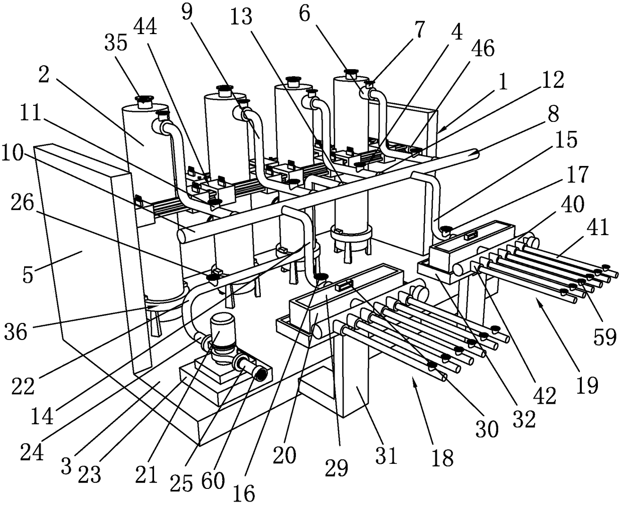
[0011] The purpose of the present invention is to provide a technical scheme of a liquid oxygen intelligent control gas supply system and its installation method in view of the deficiencies in the prior art. The overall structure design is reasonable, and the continuity of liquid oxygen can be realized through multiple liquid oxygen storage tanks. supply, and limit and fix the upper part of the liquid oxygen storage tank through the limit frame assembly, improve the safety performance of the liquid oxygen storage tank and reduce potential safety hazards. When a problem occurs, the spare branch assembly can be opened to ensure continuous oxygen supply without affecting the internal maintenance of the main branch assembly, and the liquid oxygen in the oxygen supply process can be filtered and screened through the filter box to remove impurity particles in the liquid oxygen , to prevent it from entering subsequent pipelines or equipment and causing damage

Method used


Image

  • Intelligent-control liquid oxygen supply system and mounting method thereof
  • Intelligent-control liquid oxygen supply system and mounting method thereof
  • Intelligent-control liquid oxygen supply system and mounting method thereof

Examples


Embodiment Construction

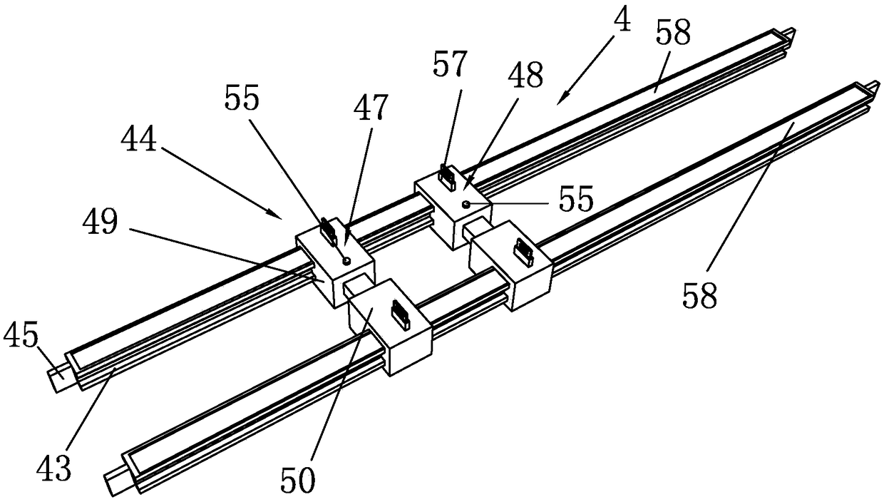
[0054] Such as Figure 1 to Figure 7 As shown, it is a liquid oxygen intelligent control gas supply system of the present invention, which includes a fixed bracket 1, a liquid oxygen storage tank 2 and a liquid supply pipeline assembly, and a pressure relief valve 35 is arranged on the top surface of the liquid oxygen storage tank 2. The bottom of the oxygen storage tank 2 is provided with a fixed support 36, the fixed support 36 includes a limit chuck 37 and a support leg 38, and the support leg 38 is evenly arranged on the bottom surface of the limit chuck 37, and the outer surface of the liquid oxygen storage tank 2 An extension block 39 is evenly arranged on the circumferential surface, and the liquid oxygen storage tank 2 is clamped in the limit chuck 37 through the extension block 39. The design of the pressure relief valve 35 can protect the liquid oxygen storage tank 2 to a certain extent, and the The design of the support 36 can support the liquid oxygen storage tank ...


PUM


Abstract

The invention discloses an intelligent-control liquid oxygen supply system and a mounting method thereof. The intelligent-control liquid oxygen supply system comprises a fixing support, liquid oxygenstorage tanks and a liquid supply pipeline component and is characterized in that the fixing support comprises a fixing plate and a limit rack component, the upper sides of the liquid oxygen storage tanks are clamped into the limit rack component, the liquid supply component comprises a liquid supply main pipe component and a liquid supply branch pipe component, and the liquid supply branch pipe component comprises a main branch pipe component and a standby branch pipe component. The mounting method includes the steps of a, mounting the liquid oxygen storage tanks; b, mounting a filter tank; c, mounting the liquid supply pipeline component; d, mounting a cleaning component. The intelligent-control liquid oxygen supply system has the advantages that continuous liquid oxygen supply can be achieved by the multiple liquid oxygen storage tanks, and the upper portions of the liquid oxygen storage tanks are limited and fixed through the limit rack component; meanwhile, by the main branch pipecomponent and the standby branch pipe component, the standby branch pipe component can be used when the main branch pipe component fails to guarantee continuous oxygen supply; the filter tank can filter and screen the supplied liquid oxygen to remove impurity particles in the liquid oxygen.

Description

technical field [0001] The invention relates to a liquid oxygen intelligent control gas supply system and an installation method thereof. Background technique [0002] Under normal temperature and high pressure, the mass of the same volume of liquid oxygen is about 270-300 times larger than that in the reference or standard state, which greatly improves the storage and transportation of liquid oxygen, and more importantly, the utilization of liquid oxygen is more convenient ,flexible. Compressed liquid oxygen is widely used in fields such as medical treatment and industrial production. [0003] The utilization of compressed liquid oxygen has the following characteristics: [0004] 1. "Point-to-point" supply increases the scope of supply; [0005] 2. The supply scale is highly elastic; [0006] 3. There are various modes of transportation, and the transportation volume can be adjusted flexibly; [0007] 4. Easy access to backup gas source; [0008] 5. Wide range of appl...

Claims


Application Information

Patent Timeline
IPC IPC(8): F17D3/01F17D1/08F17D1/14
CPCF17D3/01F17D1/08F17D1/14
Inventor 吴林彬沈静君王斌旭
Owner 宁波奉天海供氧净化成套设备有限公司
Learn More