Push rod mechanism with automatic retraction function

A technology of push rod mechanism and function, which is applied in the field of push rod mechanism, can solve the problems that the missing gear cannot be the driving force of the rack, the contact between the gear and the rack is discontinuous, and the noise is large, so that it is not easy to jam the teeth, the structure is simple, low noise effect

Pending Publication Date: 2018-11-23
TONELUCK PROD TECH (HUIZHOU) CO LTD
View PDF0 Cites 3 Cited by
  • Summary
  • Abstract
  • Description
  • Claims
  • Application Information

AI Technical Summary

Problems solved by technology

The existing automatic opening mechanism of doors and drawers usually adopts the following method: a mechanism composed of toothless gears, racks and extension springs is used. The toothless gears drive the racks to extend. The missing tooth is connected to the rack. At this time, the missing tooth gear cannot be the driving force for the rack, and the rack is pulled back by the spring to reset
However, this structure has the following disadvantages: the contact between the gear and the rack is discontinuous, resulting in high noise when just in contact, and it is easy to get stuck

Method used


Image

  • Push rod mechanism with automatic retraction function
  • Push rod mechanism with automatic retraction function
  • Push rod mechanism with automatic retraction function

Examples


Embodiment 1

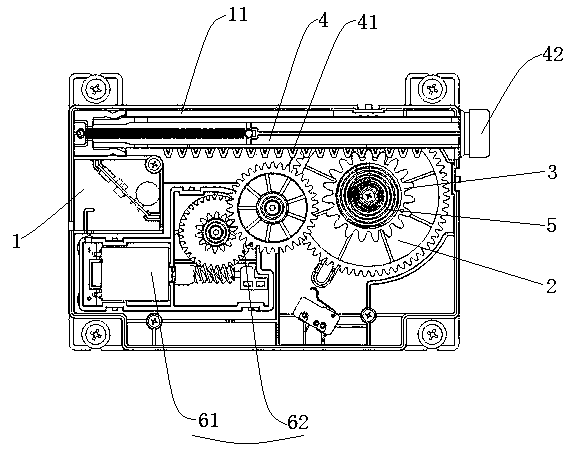
[0032] refer to Figure 1~9 , a push rod mechanism with automatic retraction function, including a housing 1, a driving wheel 2, a driving gear 3, a push rod 4 and an installation shaft 5, the installation shaft 5 is fixedly installed on the housing 1, and the The driving wheel 2 and the driving gear 3 are successively installed on the mounting shaft 5 from bottom to top. The housing 1 can be provided with a slideway 11 matching the push rod 4, and the push rod 4 is installed in the slideway 11, so that the push rod 4 can expand and contract in the slideway of the housing 1, wherein the push rod 4 can only Do telescopic movement in sliding without other movements such as lifting or rotating. The push rod 4 is provided with a rack 41, and the drive gear 3 is engaged with the rack 41, so that the drive gear 3 drives the push rod 4 to expand and contract longitudinally. The drive gear 3 can move axially along the installation shaft 5 on the installation shaft 5, so as to realiz...

Embodiment 2

[0044] refer to Figure 10 , the main structure of this embodiment is the same as that of Embodiment 1, the difference lies in the structure of the driving gear 3, and the connection mode between the driving wheel 2 and the driving gear 3, as follows:

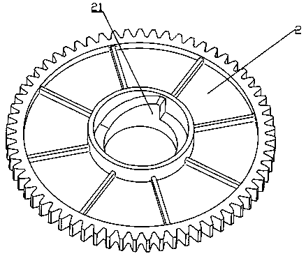
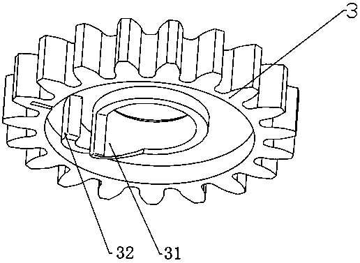
[0045] The lower side of the drive gear 3 is provided with only one screw table, that is, the third screw table 33. The width of the third screw table 33 is wider, which is about the sum of the width of the first screw table 51 and the first card table 21. . The lower side of the third helical table 33 is opposite to the upper side of the first helical table 51, and the third helical table 33 can slide relative to the first helical table 51; the rear side of the third helical table 33 is in contact with The front sides of the first clamping platform 21 are oppositely arranged, and the driving wheel 2 drives the driving gear 3 to rotate through the first clamping platform 21 pushing the third screw platform 33 . The height of ...


PUM


Abstract

The invention discloses a push rod mechanism with an automatic retraction function, and belongs to the technical field of extension and retraction mechanical structures. A push rod of the push rod mechanism can be automatically retracted after being extended. The technical scheme mainly includes that the push rod mechanism comprises a shell (1), a driving wheel (2), a driving gear (3), the push rod (4) and a mounting shaft (5); the mounting shaft (5) is fixedly mounted on the shell (1), and the driving wheel (2) and the driving gear (3) are mounted on the mounting shaft (5); a rack (41) is arranged on the push rod (4), and the driving gear (3) meshes with the rack (41), so that the push rod (4) can be driven to be longitudinally extended and retracted; the driving gear (3) can move on themounting shaft (5) along the axial direction of the mounting shaft (5), so that the driving gear (3) and the driving wheel (2) can be clamped with each other and can be separated from each other; thedriving gear (3) and the driving wheel (2) can be automatically reset after being separated from each other. The push rod mechanism has the advantage that the push rod mechanism can be used for opening and closing doors and drawers of products such as refrigerators.

Description

technical field [0001] The invention relates to the technical field of retractable mechanical structures, in particular to a push rod mechanism with automatic retraction function. Background technique [0002] With the continuous progress of society and the development of science and technology, it is the general trend for all kinds of home appliances to develop in the direction of intelligence and humanization. The doors and drawers of electrical appliances need more intelligent and humanized designs to meet the needs of the market. The automatic opening function of doors and drawers is a common design of home appliances nowadays. The existing automatic opening mechanism of doors and drawers usually adopts the following method: a mechanism composed of toothless gears, racks and extension springs is used. The toothless gears drive the racks to extend. The tooth-missing part is connected with the rack. At this time, the tooth-missing gear cannot be the driving force for the ...

Claims


Application Information

Patent Timeline
Patent Type & Authority Applications(China)
IPC IPC(8): E05F15/619F25D23/02
CPCF25D23/028E05F15/619E05Y2900/31
Inventor 黄紫虹吴建成
Owner TONELUCK PROD TECH (HUIZHOU) CO LTD
Why Eureka
Try Eureka