Plate hook and quick lifting method thereof

A technology of plate hook and hook body, which is applied in the direction of load hanging components, transportation and packaging, safety devices, etc., can solve the problems of inability to hook safely, accurately, and efficiently, and achieve convenient adjustment of installation angle, convenient replacement and maintenance, and saving The effect of power consumption

Active Publication Date: 2018-11-23
SHANGHAI MEISHAN IRON & STEEL CO LTD
View PDF6 Cites 7 Cited by
  • Summary
  • Abstract
  • Description
  • Claims
  • Application Information

AI Technical Summary

Problems solved by technology

[0004] The present invention aims at the problems existing in the existing inventions, and provides a plate hook. The invention has a compact structure, convenient disassembly and assembly, and is safe and reliable. , The invention problem of high-efficiency hooking

Method used


Image

  • Plate hook and quick lifting method thereof
  • Plate hook and quick lifting method thereof
  • Plate hook and quick lifting method thereof

Examples


Embodiment 1

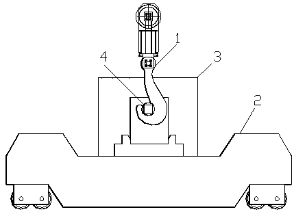
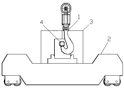
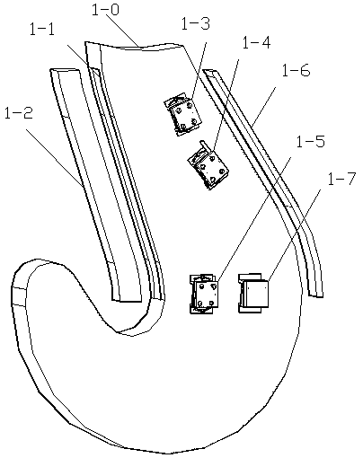
[0029] Embodiment 1: see Figure 3-7 As shown, a plate hook 1 includes a hook body 1-0, a magnetic strip 1-2, a photoelectric sensor 1-3, a camera 1-4, a proximity switch 1-5, a high temperature resistant light strip 1-6, and a battery pack 1 -7 and so on. A groove 1-1 with a width of 1 / 3 of the thickness of the plate hook is provided on the inner wall between the half of the vertical height of the hook body 1-0 and the tangent point between the inner wall of the hook body and the hook center circle, and the groove 1-1 is nested Magnetic strips 1-2 made of NdFeB permanent magnets are installed. A photoelectric sensor box 1-8, a camera box 1-9, a proximity switch box 1-10 and a battery pack box 1-11 are sequentially installed on the outside of the hook head of the hook body from top to bottom. Photoelectric sensors 1-3, cameras 1-4, proximity switches 1-5, and battery packs 1-7 are respectively nested and installed in various boxes. On the outer wall of the hook body 1-0, an...


PUM


Abstract

The invention relates to a plate hook and a quick lifting method thereof. The plate hook comprises a hook body, a magnetic strip, a photoelectric sensor, a camera, a proximity switch, a high-temperature resisting lamp strip and a battery set; a groove is formed in the inner wall at the middle lower part of the hook body; the magnetic strip is embedded and mounted in the groove; the photoelectric sensor, the camera, the proximity switch and the battery set are mounted on the outer side of a hook head of the hook body in sequence from top to bottom; and the high-temperature resisting lamp stripis mounted on the outer wall of the hook body. The plate hook is compact in structure, convenient to disassemble, safe and reliable, and mainly solves the problems of incapability of safely, preciselyand efficiently hanging the hook in traditional steel ladle lifting operation process.

Description

field of invention [0001] The invention relates to a plate hook, in particular to a plate hook and a quick lifting method thereof, belonging to the invention field of metallurgical steelmaking equipment. Background technique [0002] see figure 1 , 2 As shown, in the field of modern metallurgical industry, the plate hook of the bridge crane is often used to realize the lifting operation of the ladle. However, in the actual lifting operation, due to the large lifting height, large dust on site, low illumination, blind area of ​​sight, shaking of the hook, etc., the driver of the bridge crane often cannot effectively see and accurately determine the status of the hook 1 hook. Affect ladle 3 hoisting operation efficiency and reliability. Even appear plate hook 1 hook tip position and be easy to be hung on ladle trunnion 4, make ladle 3 lifting decoupling accidents take place very easily in the hoisting process, bring great potential safety hazard to normal production. [00...

Claims


Application Information

Patent Timeline
Patent Type & Authority Applications(China)
IPC IPC(8): B66C1/40B66C13/46B66C13/16B66C15/06
CPCB66C1/40B66C13/16B66C13/46B66C15/065
Inventor 曹艳玲陈绍林
Owner SHANGHAI MEISHAN IRON & STEEL CO LTD
Why Eureka
Try Eureka