Unwinding mechanism for reel rewinding equipment and application thereof
A technology of unwinding mechanism and winding mechanism, which is applied in the direction of winding strips, thin material processing, transportation and packaging, etc., which can solve the problems of unwinding equipment, uneven rewinding, paper breakage, etc., and achieve The effect of simple structure, fast learning speed and short learning time
- Summary
- Abstract
- Description
- Claims
- Application Information
AI Technical Summary
Problems solved by technology
Method used
Image
Examples
Embodiment 1
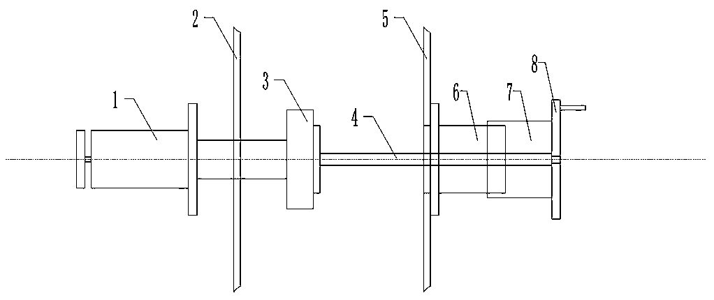
[0030] An unwinding mechanism 10 of reel rewinding equipment, comprising: an unwinding mechanical shaft 1, an equipment wall plate 2, a magnetic powder brake 3, a connecting sliding shaft 4, an equipment wall plate 5, an external thread sleeve 6, an internal thread sleeve 7, and a handle 8. The specific connection method of the unwinding mechanism is that the shaft behind the unwinding mechanical shaft 1 is designed to slide laterally in the support bearing on the equipment wall plate 2, and pass through the magnetic powder brake 3 and fix it with an end cover. One end of the connecting slide shaft 4 is bolted to the magnetic powder brake 3, and the other end slides in the external threaded sleeve 6, fixed by a key without rotation, and the end of the connecting sliding shaft 4 is connected with the handle 8. Internally threaded sleeve 7 is connected with handle 8 together. When the handle 8 is rotated positively and negatively, the internally threaded sleeve 7 and the externa...
Embodiment 2
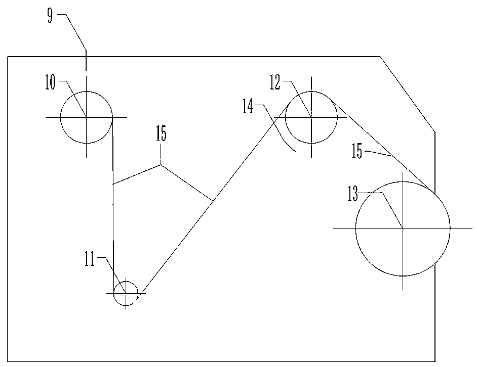
[0032]A reel rewinding device, comprising: a device body 16, an ultrasonic probe one 9, an unwinding mechanism 10, a meter counting mechanism 11, a rewinding mechanism 13, and an ultrasonic probe two 14. Ultrasonic probe one 9, unwinding mechanism 10, meter counting mechanism 11, winding mechanism 13, and ultrasonic probe two 14 are all located on the same side of the device body 16, and ultrasonic probe one 9 is located on the upper part of the unwinding mechanism 10 for detecting the unwinding reel The angular velocity of the reel, the outer diameter of the reel and the disadvantages. The ultrasonic probe 2 14 is located on the upper part of the winding mechanism 13 to detect the angular velocity and the outer diameter of the reel. The meter meter mechanism 11 is located in the unwinding mechanism 10 Between the unwinding mechanism 10 and the winding mechanism 13 , the paper travel path is that the unwinding mechanism 10 passes through the meter counting mechanism 11 and then...
Embodiment 3
[0034] A reel rewinding device, comprising: a device body 16, an ultrasonic probe one 9, an unwinding mechanism 10, a meter counting mechanism 11, a deviation correction mechanism 12, a rewinding mechanism 13, and an ultrasonic probe two 14. Ultrasonic probe one 9, unwinding mechanism 10, meter counting mechanism 11, deviation correction mechanism 12, winding mechanism 13, ultrasonic probe two 14 are all located on the same side of the equipment body 16, and ultrasonic probe one 9 is located on the top of the unwinding mechanism 10 for detecting The angular velocity of the unwinding reel, the outer diameter of the reel and the defects. The ultrasonic probe 2 14 is located on the upper part of the winding mechanism 13 to detect the angular velocity and the outer diameter of the reel. The meter meter mechanism 11 and The deviation correcting mechanism 12 is located between the unwinding mechanism 10 and the winding mechanism 13, and the paper travel path is that the unwinding mec...
PUM
 Abstract
Description
Claims
Application Information
 - R&D
- Intellectual Property
- Life Sciences
- Materials
- Tech Scout
- Unparalleled Data Quality
- Higher Quality Content
- 60% Fewer Hallucinations
Browse by: Latest US Patents, China's latest patents, Technical Efficacy Thesaurus, Application Domain, Technology Topic, Popular Technical Reports.
© 2025 PatSnap. All rights reserved.Legal|Privacy policy|Modern Slavery Act Transparency Statement|Sitemap|About US| Contact US: help@patsnap.com


