
Rotatable lifting type pneumatic clamping device

A technology of rotary lifting and pneumatic clamping, applied in the directions of transportation and packaging, conveyor objects, etc., can solve the problems of operator's personal safety threat, high physical strength requirements of porters, inability to rotate and move up and down, and achieve simple and practical structure. Strong, low-cost effect

Inactive Publication Date: 2018-11-23
JIANGSU UNIV
View PDF9 Cites 6 Cited by
  • Summary
  • Abstract
  • Description
  • Claims
  • Application Information

AI Technical Summary

Problems solved by technology

In the prior art, most of the clamping mechanisms can only realize the clamping function, and cannot rotate and move up and down
When it is necessary to place the items in a certain position, it cannot meet the actual needs, and it still needs to be carried manually. In the process, it is inevitable that the transported items will be bumped, reducing the accuracy of the items, and the physical requirements for the porters are very high. High, need to spend a lot of manpower and material resources
At the same time, due to the unskilled operation of the operator, it is easy to cause damage to the product and pose a certain threat to the personal safety of the operator.

Method used


Image

  • Rotatable lifting type pneumatic clamping device
  • Rotatable lifting type pneumatic clamping device
  • Rotatable lifting type pneumatic clamping device

Examples


Embodiment Construction

[0030] The present invention will be further described below in conjunction with the accompanying drawings and specific embodiments, but the protection scope of the present invention is not limited thereto.

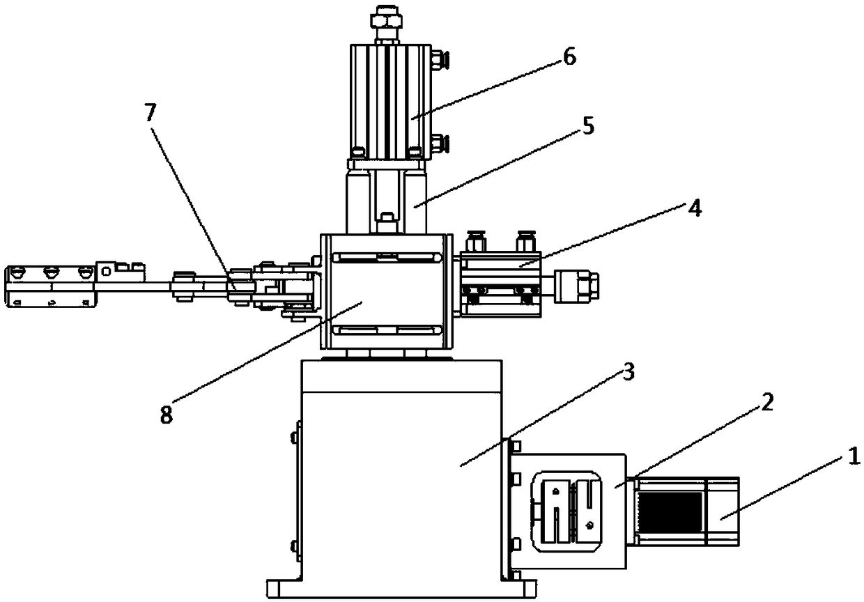
[0031] Such as Figure 1-3 As shown, a rotatable lifting pneumatic clamping device according to the present invention includes a helical gear shaft 11, a stepped shaft 25, a second helical gear 27, a first box body 3, a second box body 8, and a first cylinder 4. Guide rail rod 5, second air cylinder 6 and clamping mechanical arm 7. The helical gear shaft 11 is coaxially provided with a first tapered roller bearing 13, a second tapered roller bearing 14, a first neck flange 29 and two first snap rings 12, the first tapered roller bearing 13 and the second The tapered roller bearings 14 are installed symmetrically, the first tapered roller bearing 13 is axially positioned by two first snap rings 12, the second tapered roller bearing 14 is positioned by the shoulder on the ...


PUM


Abstract

The invention relates to the field of clamping mechanisms of automation equipment and provides a rotatable lifting type pneumatic clamping device. The rotatable lifting type pneumatic clamping devicecomprises a helical gear shaft, a stepped shaft, a second helical gear which is mounted on the stepped shaft, a first box body, a second box body, a first air cylinder, guide rail rods, a second air cylinder and a clamping mechanical arm; the helical gear shaft is connected with a motor; a first helical gear on the helical gear shaft is engaged with the second helical gear; the guide rail rods arecoaxially fixed to the top end of the stepped shaft; the second box body sleeves the guide rail rods; the second air cylinder is fixedly connected with the top ends of the guide rail rods; a second push rod of the second air cylinder is fixedly connected with the second box body; and the clamping mechanical arm is mounted on the second box body and controlled by the first air cylinder. The rotatable lifting type pneumatic clamping device can realize the functions of rotating, lifting, material taking, discharging and the like in an article clamping process, and the article clamping reliability and efficiency are improved.

Description

technical field [0001] The invention relates to the field of clamping mechanisms of automation equipment, in particular to a rotatable lifting pneumatic clamping device. Background technique [0002] Grippers are widely used in automated production lines to achieve workpiece clamping operations. With the improvement of the automation level of various industries, grippers are not only widely used in traditional industrial fields, but also gradually penetrated into fields such as medical treatment, food, service robots, and seabed exploration. In order to meet the needs of multiple varieties and different environments, the The design and performance of the gripper put forward new requirements. In the prior art, most of the clamping mechanisms can only realize the clamping function, and cannot rotate and move up and down. When it is necessary to place the items in a certain position, it cannot meet the actual needs, and it still needs to be carried manually. In the process, i...

Claims


Application Information

Patent Timeline
Patent Type & Authority Applications(China)
IPC IPC(8): B65G47/91
Inventor 顾寄南康颜奎伊孟舒冒文彦燕瑾瑾黄飞虎
Owner JIANGSU UNIV
Learn More